
Zigzag sewing machine

A sewing machine, a zigzag technology, applied in the direction of sewing machine components, sewing machine needle holder, sewing machine ring mechanism, etc., can solve the problems such as inability to sew

Active Publication Date: 2020-11-10
CHEE SIANG IND CO LTD +1
View PDF7 Cites 0 Cited by
  • Summary
  • Abstract
  • Description
  • Claims
  • Application Information

AI Technical Summary

Problems solved by technology

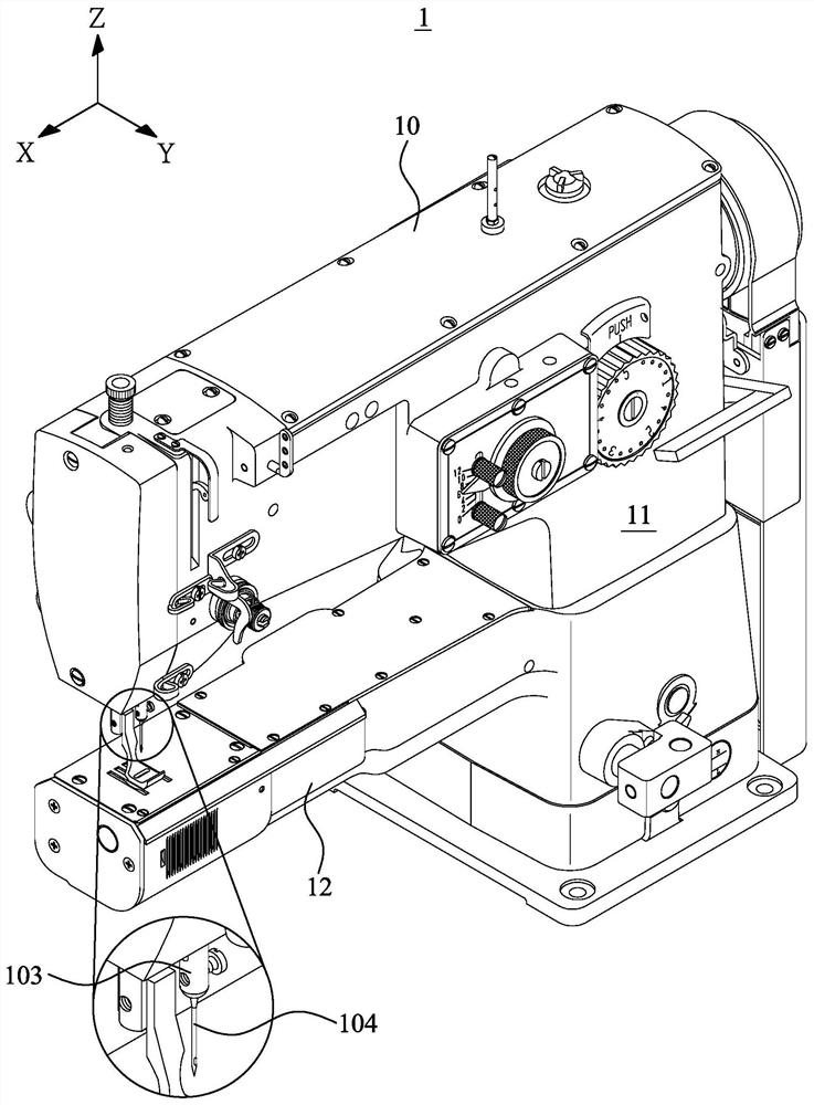
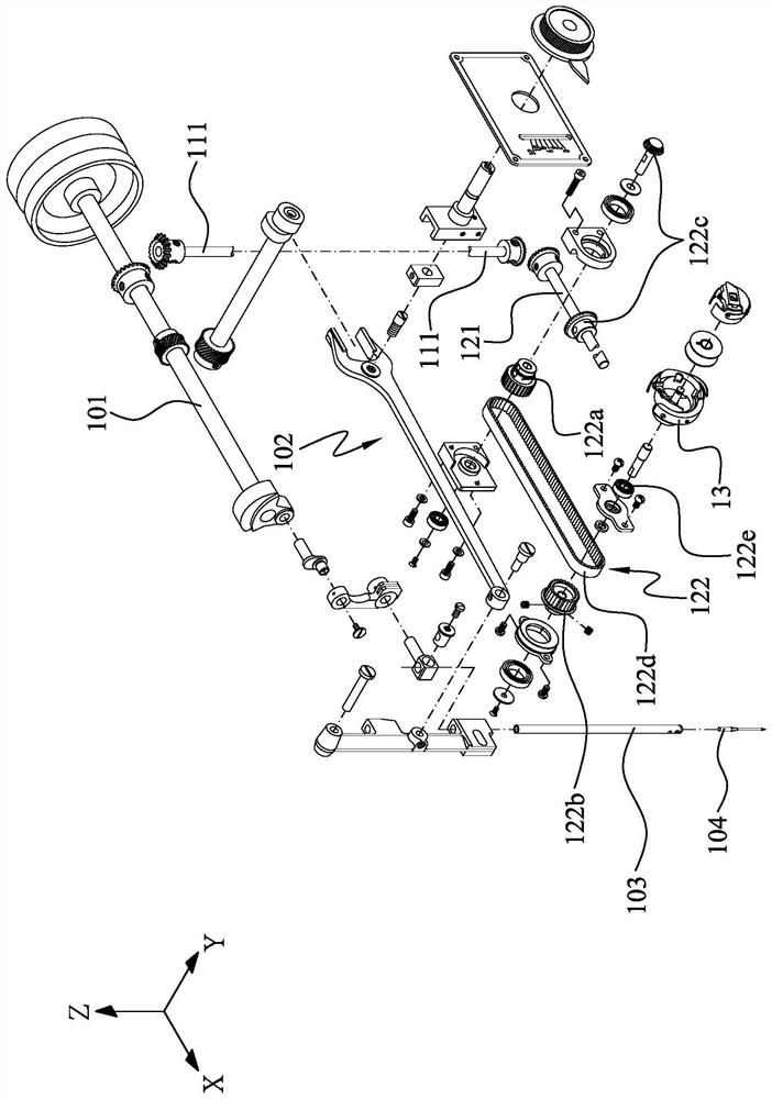
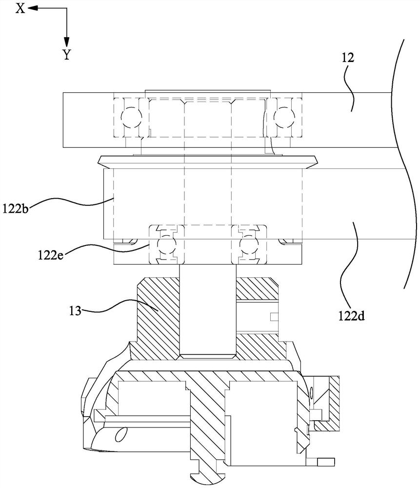
[0005] However, when the second pulley 122b of the transmission mechanism 122, the ball bearing 122e of the transmission mechanism 122, and the rotary hook 13 are assembled together, the ball bearing 122e and the second pulley 122b are arranged in the Y-axis direction of the rotary hook 13 in sequence, so that The ball bearing 122e, the second pulley 122b and the rotary hook 13 are arranged in series along the Y-axis direction, and the Y-axis direction of the lower tube base 12 must have sufficient front and rear lengths to accommodate the ball bearing 122e and the second pulley at the same time. 122b and rotary hook 13, resulting in the large front and rear length of the lower pipe seat 12, the existing zigzag sewing machine 1 cannot perform the sewing operation of shoe mouth hemming for smaller shoe models.

Method used


Image

  • Zigzag sewing machine
  • Zigzag sewing machine
  • Zigzag sewing machine

Examples


Embodiment Construction

[0028] The present invention will be further described below in combination with specific embodiments and accompanying drawings, and the advantages and characteristics of the present invention will become clearer along with the description.

[0029] see Figure 4 and Figure 5 As shown, the zigzag sewing machine 2 of the present invention has a body 20, the body 20 has a head 21 and a pillar 22, the inside of the head 21 has an upper shaft 23 parallel to the X axis, and the upper shaft 23 is connected to a needle bar 24, when the upper shaft 23 rotates around the X-axis direction, the upper shaft 23 can drive the needle bar 24 to move up and down along the Z-axis direction, so that a machine needle 25 connected to the needle bar 24 is synchronously moved along the Move back and forth along the Z-axis direction, as shown in the figure, the needle bar 24 is equipped with a swing mechanism 26 located inside the headstock 21, the swing mechanism 26 is connected to the upper shaft...


PUM


Abstract

The invention relates to a zigzag sewing machine. The zigzag sewing machine is provided with a lower pipe seat, a lower shaft, a transmission mechanism and a rotating shuttle, wherein the lower shaftis connected to the transmission mechanism and rotates in the lower pipe seat with the X-axis direction as the axis, the lower shaft can drive an outer kettle of a rotating shuttle to rotate with theY-axis direction as the axis through the transmission mechanism, and the transmission mechanism is provided with a rotating shuttle seat, a bearing and a transmission part; the rotating shuttle seat is arranged in the Y-axis direction of the outer kettle and form a penetrating part arranged in the outer kettle, an accommodating space is formed between the penetrating part and the outer kettle, thebearing is positioned in the accommodating space, the transmission piece is connected to the outer part of the outer kettle, and the transmission piece, the bearing and the penetrating part are sequentially arranged from the outer part of the inner kettle to the inner part of the outer kettle; the end part volume of the lower pipe seat can be reduced along the Y direction through the assembling state of the rotating shuttle seat, the bearing, the outer kettle and the transmission part, so that the zigzag sewing machine can perform sewing operation of welt edge covering on shoes with smaller sizes.

Description

technical field [0001] The invention relates to a zigzag sewing machine which can produce zigzag stitches through the reciprocating swing of machine needles perpendicular to the feeding direction, in particular to a cylindrical zigzag sewing machine which can sew small size shoe models. Background technique [0002] The sewing machine is mainly to combine several layers of sewing materials with each other through sewing, and, with the continuous evolution of technology, there are many styles of sewing machines on the market, and different styles of sewing machines can be applied to different cars. The sewing operation of sewing things, wherein, there is a zigzag sewing machine that can produce zigzag stitches by swinging machine needles on the surface of shoes, bags or cylinders. [0003] see figure 1 and figure 2 As shown, the existing zigzag sewing machine 1 has a headstock 10 and a pillar 11. The bottom of the pillar 11 extends along the X-axis direction to form a lowe...

Claims


Application Information

Patent Timeline
IPC IPC(8): D05B3/02D05B55/14D05B57/30
CPCD05B3/02D05B55/14D05B57/30
Inventor 陈旭辉
Owner CHEE SIANG IND CO LTD
Learn More