
Permanent-magnet direct-drive locomotive and drive suspension damping device thereof

A suspension shock-absorbing, direct-drive locomotive technology, applied to the transmission device driven by an electric motor, etc., can solve the problems of poor vibration damping effect and poor displacement ability, and achieve no wear, prolong the life cycle, and strong displacement ability Effect

Active Publication Date: 2020-11-10
DATONG ELECTRIC LOCOMOTIVE OF NCR
View PDF8 Cites 0 Cited by
  • Summary
  • Abstract
  • Description
  • Claims
  • Application Information

AI Technical Summary

Problems solved by technology

[0004] However, the existing direct drive motors have poor displacement ability and poor vibration damping effect when they are suspended on the frame.

Method used


Image

  • Permanent-magnet direct-drive locomotive and drive suspension damping device thereof
  • Permanent-magnet direct-drive locomotive and drive suspension damping device thereof
  • Permanent-magnet direct-drive locomotive and drive suspension damping device thereof

Examples


Embodiment Construction

[0033] Example embodiments will now be described more fully with reference to the accompanying drawings. Example embodiments may, however, be embodied in many forms and should not be construed as limited to the embodiments set forth herein; rather, these embodiments are provided so that this disclosure will be thorough and complete, and will fully convey the concept of example embodiments to those skilled in the art. The same reference numerals in the drawings denote the same or similar structures, and thus their detailed descriptions will be omitted.

[0034] Although relative terms such as "upper" and "lower" are used in this specification to describe the relative relationship of one component of an icon to another component, these terms are used in this specification only for convenience, for example, according to the description in the accompanying drawings directions for the example described above. It will be appreciated that if the illustrated device is turned over so...


PUM


Abstract

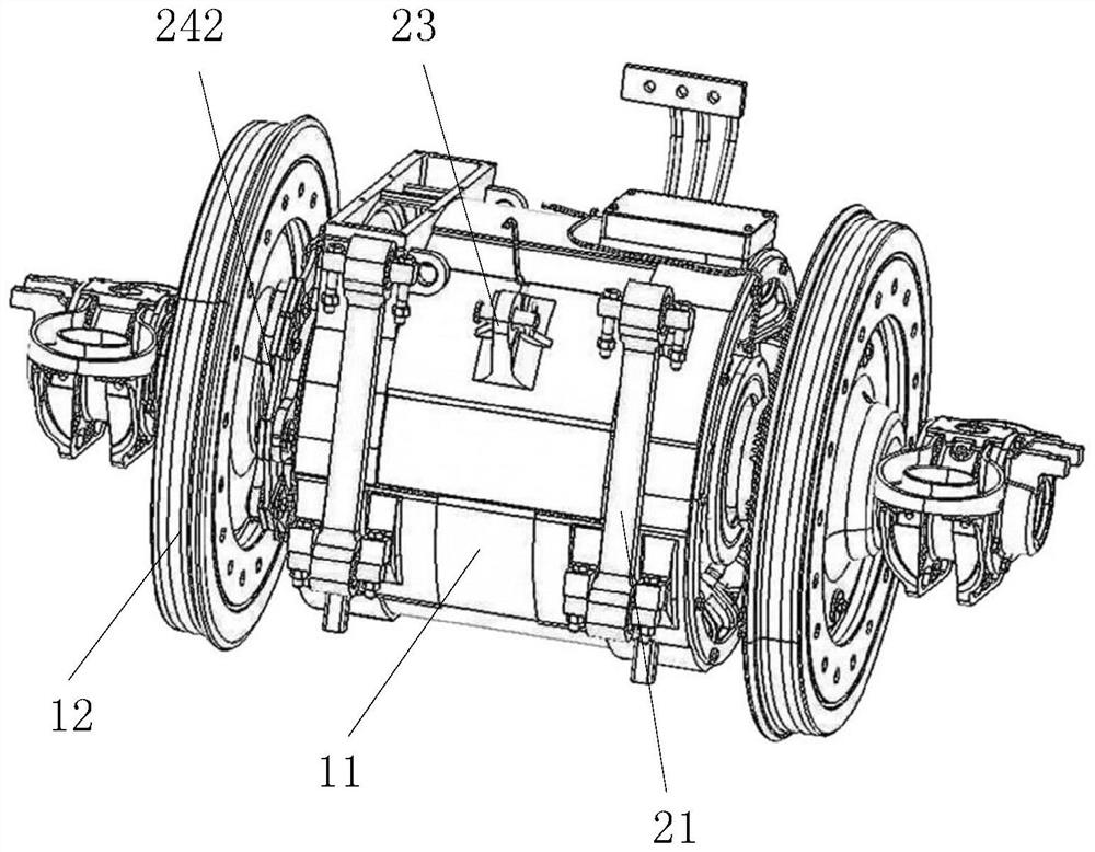
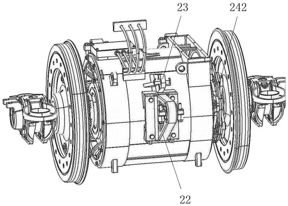
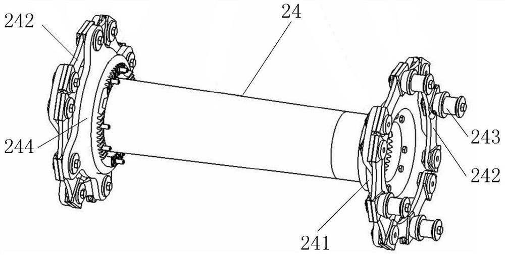
The invention relates to a permanent magnet direct drive locomotive and a drive suspension damping device thereof. The damping device comprises a suspension rod assembly, a suspension arm and a flexible plate diaphragm. A first rotating shaft is arranged in a first rubber joint of the suspender assembly in a penetrating mode, a second rotating shaft is arranged in a second rubber joint in a penetrating mode, and the suspender assembly can be connected with a driving motor through the first rotating shaft and can be connected with a frame through the second rotating shaft; the suspension arm can be connected with a drive through the base and can be connected with a frame through a third rotating shaft; a transmission disc is arranged at the first end of a hollow shaft of a rotor of the driving motor, and a plurality of first disc claws extend out of the transmission disc. A force transmission disc is arranged at the second end of the hollow shaft, and a plurality of second disc claws extend out of the force transmission disc; the flexible plate membrane is used for being arranged on the side, away from the second grabbing disc, of the first disc claw, the transmission pin is arranged on the side, away from the first disc claw, of the flexible plate membrane, and the transmission pin and the first disc claw are arranged on the flexible plate membrane in a staggered mode.

Description

technical field [0001] The present disclosure relates to the technical field of railway locomotives, in particular, to a permanent magnet direct drive locomotive and a drive suspension vibration damping device thereof. Background technique [0002] Permanent magnet direct drive technology is a recognized next-generation drive technology in the railway locomotive industry. The advantages of permanent magnet synchronous motors, such as high power density, high power factor, and high overload capacity, make permanent magnet system research and development a new generation of rail transit equipment research trend. The permanent magnet direct drive traction system adopts the permanent magnet synchronous motor to directly drive the wheel set technology, and the gearbox is eliminated. This transmission mode has the advantages of simple structure, high transmission efficiency, green energy saving, etc., and is the development direction of the next generation locomotive traction drive...

Claims


Application Information

Patent Timeline
Patent Type & Authority Applications(China)
IPC IPC(8): B61C9/48
CPCB61C9/48
Inventor 李华李前王良涛岳娟史建飞
Owner DATONG ELECTRIC LOCOMOTIVE OF NCR
Learn More