Drawing wire measuring and calibrating equipment, system and method

A technology for calibrating equipment and pulling wires, applied in the field of measurement, can solve problems such as high difficulty in use, inability to achieve results, and limited accuracy, and achieve the effects of accurate cable length changes, improved user experience, and accurate measurement and calibration

Active Publication Date: 2021-08-03
深圳市智流形机器人技术有限公司
View PDF4 Cites 0 Cited by
  • Summary
  • Abstract
  • Description
  • Claims
  • Application Information

AI Technical Summary

Problems solved by technology

But laser trackers are complex to deploy, difficult to use, and expensive
Although other measuring devices can measure the trajectory changes during the robot's movement, their accuracy is limited and cannot achieve the same effect as the laser tracker.
[0004] At present, the problems of complex use of laser tracker, high price and insufficient accuracy of other measuring devices need to be solved

Method used


Image

  • Drawing wire measuring and calibrating equipment, system and method
  • Drawing wire measuring and calibrating equipment, system and method
  • Drawing wire measuring and calibrating equipment, system and method

Examples


Embodiment Construction

[0031] Unless otherwise defined, all technical and scientific terms used herein have the same meaning as commonly understood by those skilled in the art to which this disclosure belongs; the terms used herein in the description of the application are only for describing specific embodiments The purpose is not to limit the present disclosure; the terms "comprising" and "having" in the specification and claims of the present disclosure and the description of the above drawings, as well as any variations thereof, are intended to cover a non-exclusive inclusion. The terms "first", "second" and the like in the specification and claims of the present disclosure or the above drawings are used to distinguish different objects, not to describe a specific order.

[0032] Reference herein to "an embodiment" means that a particular feature, structure, or characteristic described in connection with the embodiment can be included in at least one embodiment of the present disclosure. The occ...


PUM


Abstract

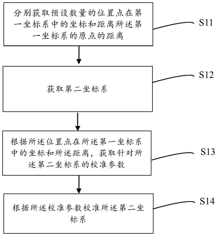
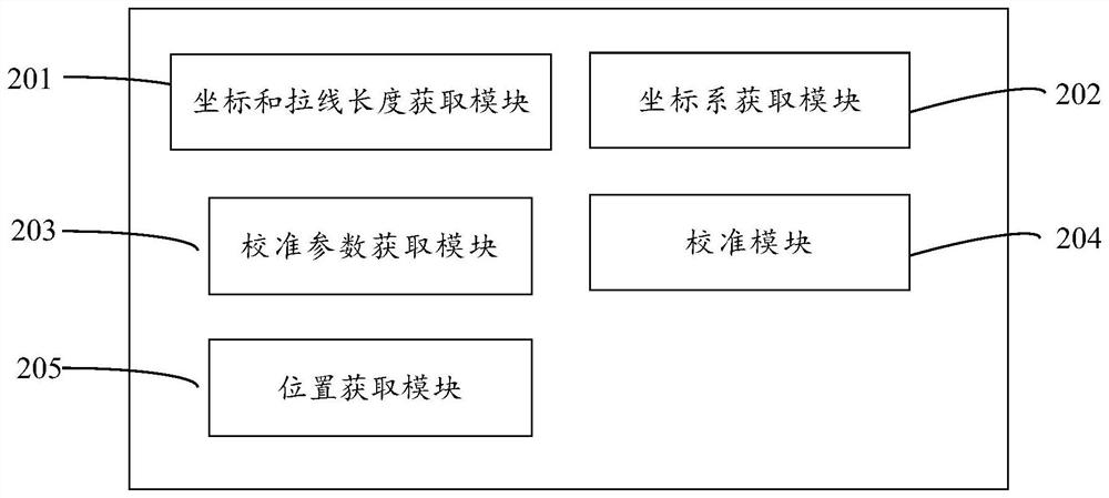
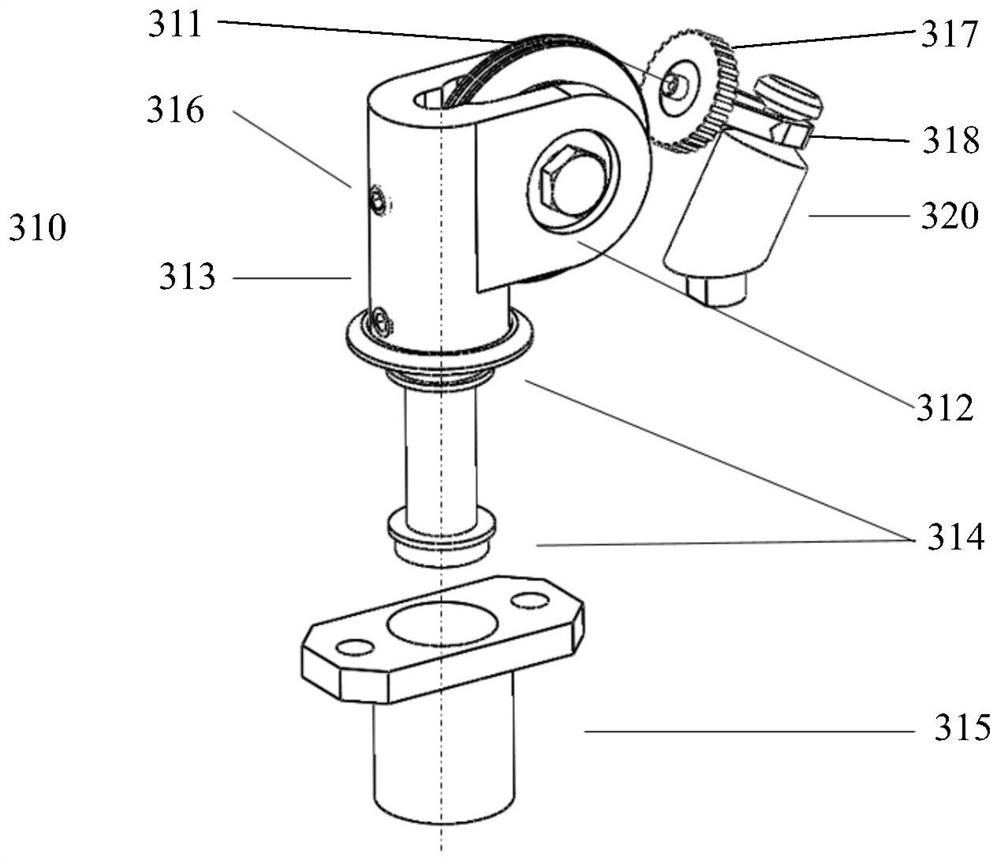
The present disclosure provides a calibration wire measurement calibration device, system and method. The drawing wire measuring and calibrating device is characterized in that it includes: a drawing wire swinging assembly, used to guide the cable pulled out and recovered by the calibration object; The cable keeps moving in a straight line when it is pulled out and recovered; the coordinate and cable length acquisition unit is used to obtain the cable length when the cable is pulled out and the coordinates of the front end of the cable; the calibration unit, according to the cable length and coordinates, Acquiring calibration parameters for the coordinate system of the object to be calibrated. The present disclosure can realize accurate measurement and calibration, is convenient to operate, and improves user experience.

Description

technical field [0001] The present disclosure relates to the field of measurement, and in particular to a wire measurement calibration device, system and method. Background technique [0002] In the manufacturing and assembly process of multi-joint robots, parts often have errors. Traditional robots use tolerances to control the overall deviation of the robot within a certain range. However, because the robot moves strictly according to the kinematics of the robot, there must be deviations between its motion model and the actual situation, which is the main reason for the limited range of robot accuracy. And with the use of the robot, the wear of the parts will aggravate this deviation, making the robot unable to complete the function more accurately. [0003] In order to solve this problem, one of the existing solutions is to use an expensive laser tracker to track the end of the assembled robot, combined with complex algorithms, to obtain the real size of the robot after...

Claims


Application Information

Patent Timeline
Patent Type & Authority Patents(China)
IPC IPC(8): B25J19/00G01B21/04G01D21/02
CPCB25J19/007B25J19/0095G01B21/04G01B21/042G01D21/02
Inventor 刘越赖长川李沛陈伯鑫郑春霞
Owner 深圳市智流形机器人技术有限公司
Why Eureka
Try Eureka