Spherical workpiece fixing method for riveting press

A fixing method and technology of a riveting press, which are applied in the cleaning methods, chemical instruments and methods, cleaning methods and utensils using gas flow, etc., can solve the problems of lack of fixing devices, etc., and achieve the effect of improving the fixing effect.

Inactive Publication Date: 2020-11-10
湖州浪佩智能科技有限公司
View PDF0 Cites 8 Cited by
  • Summary
  • Abstract
  • Description
  • Claims
  • Application Information

AI Technical Summary

Problems solved by technology

[0005] The purpose of the present invention is to solve the problem that the lower end of most traditional riveting machines lacks corresponding fixing devices, and to provide a method for fixing spherical workpieces of riveting machines that can effectively fix spherical workpieces

Method used


Image

  • Spherical workpiece fixing method for riveting press
  • Spherical workpiece fixing method for riveting press
  • Spherical workpiece fixing method for riveting press

Examples


Embodiment 1

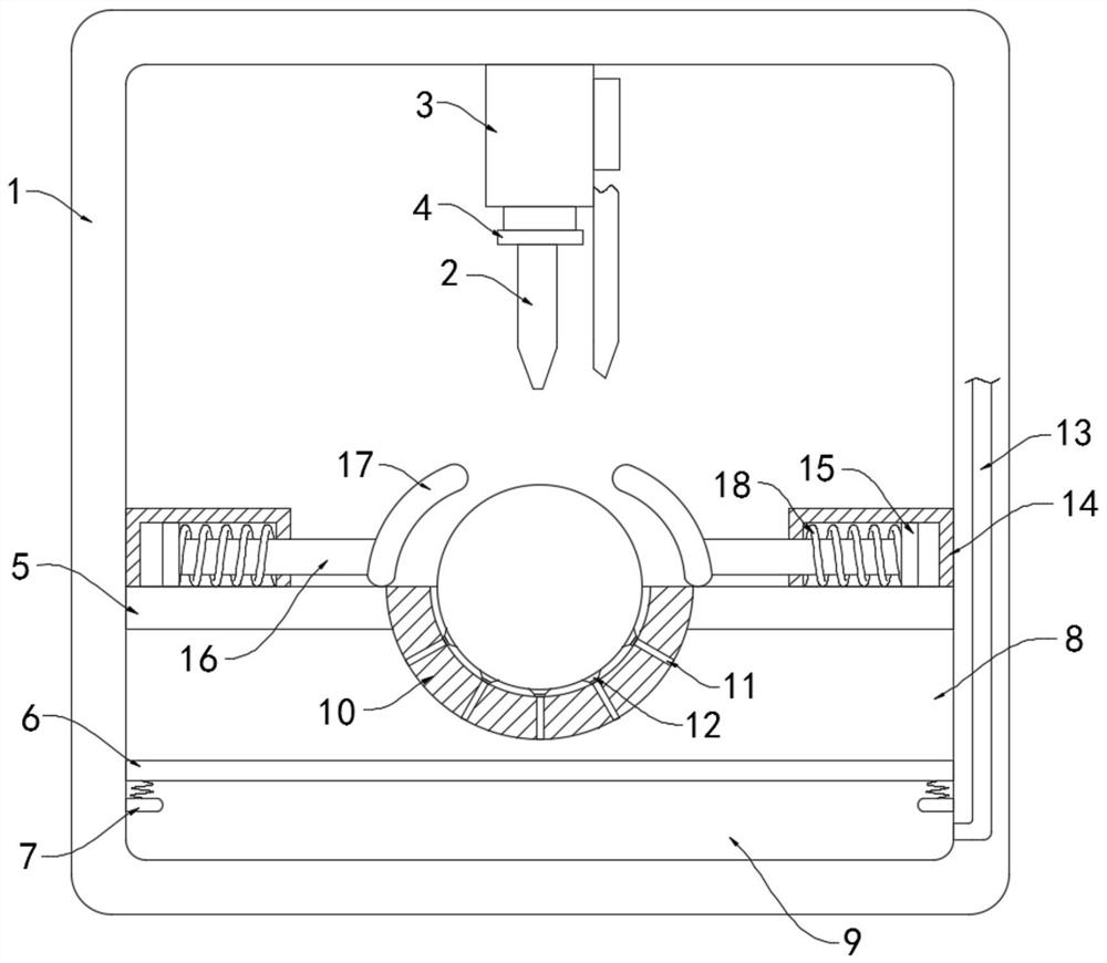
[0028] Such as Figure 1-2 As shown, a method for fixing a spherical workpiece of a riveting press, the specific fixing method is as follows:

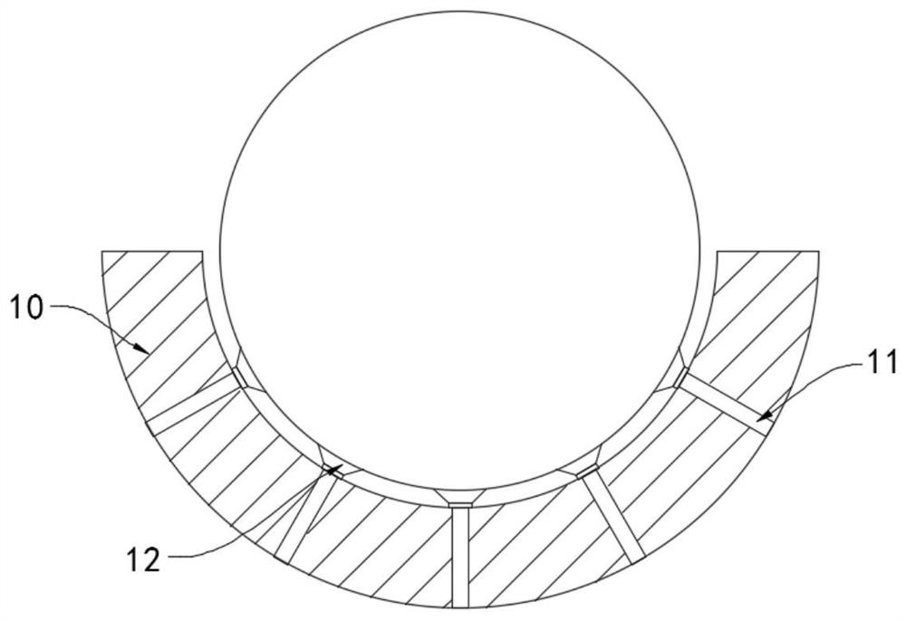
[0029] S1, placing, placing the spherical workpiece to be riveted in the fixing groove 10 on the fixing table 5;

[0030] S2. The bottom surface is fixed. When the riveting head 2 drives the magnetic ring 4 to move down, the repulsion between the magnetic block in the sliding plate 6 and the magnetic ring 4 will make the sliding plate 6 slide downward, so that the air pressure in the upper chamber 8 Reduced, the suction cup 12 will be tightly adsorbed on the lower surface of the spherical workpiece under the action of negative pressure, and the spherical workpiece will be fixed at the bottom;

[0031] S3, the side is fixed, when the riveting joint 2 drives the magnetic ring 4 to move down, the magnetic field strength in the induction coil 18 changes to make it generate current, so that the induction coil 18 shrinks, and the moving arc...

Embodiment 2

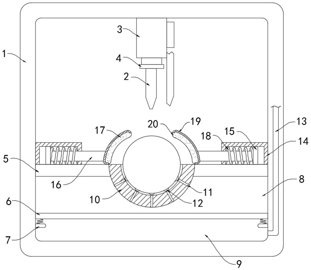
[0047] Such as Figure 3-4 As shown, the difference between this embodiment and Embodiment 1 is that the arc clamp 17 includes an outer hard shell 19 and an elastic bag 20 filled with electrorheological fluid inside the inner layer, and the elastic bag 20 is fixedly embedded There are conductive threads.

[0048] In this embodiment, when the arc clamp 17 moves toward the workpiece, the elastic capsule 20 in the soft state inside the arc clamp 17 will fit the surface of the spherical workpiece, and when the riveting head 2 is connected to the workpiece through the riveting nail, The electrorheological fluid in the arc clamp 17 will solidify when it is energized instantly, and the cured electrorheological fluid fits the surface of the workpiece more effectively, which can further effectively improve the fixing effect on the workpiece.


PUM


Abstract

The invention belongs to the field of riveting machines, and particularly relates to a spherical workpiece fixing method for a riveting press. The specific fixing method comprises the following stepsof placing, bottom surface fixing, side surface fixing, and cleaning. A fixing device is further included in the fixing process, and the fixing device comprises a fixing frame and a riveting head conducted with micro-current. A fixing base is fixedly connected to the inner top face of the fixing frame, the riveting head is fixedly installed at the lower end of the fixing base, the riveting head isfixedly sleeved with a magnetic ring, a fixing table is fixedly connected to the lower end of the fixing frame, and a horizontally-arranged sliding plate is slidably connected into the fixing table.A plurality of magnetic blocks in polar repulsion to the magnetic ring are fixedly embedded in the sliding plate. By arranging an upper cavity, when the riveting head moves downwards, repulsive forcebetween the riveting head and the magnetic blocks in the sliding plate can push the sliding plate to slide downwards, the internal space of the upper cavity is increased, the air pressure in the uppercavity is reduced, a suction cup can be tightly attracted to the lower surface of a spherical workpiece, and the spherical workpiece is fixed at the bottom.

Description

technical field [0001] The invention belongs to the field of riveting presses, in particular to a method for fixing a spherical workpiece of a riveting press. Background technique [0002] A variety of processing machines are often used in the processing of workpieces. Riveting presses are one of the more common processing devices. Riveting presses use punching machine equipment and special connecting dies to go through a momentary high-pressure processing process, which is suitable for Connection of steel plate, stainless steel plate, aluminum plate and non-metal interlayer. [0003] Before the riveting operation, the workpiece to be riveted needs to be fixed at the lower end of the riveting head. Most rectangular workpieces with standardized shapes can be placed directly at the lower end of the riveting head. However, for similar spherical workpieces, most traditional riveting machines It is just that the placement table is simply provided with a placement slot or lacks a...

Claims


Application Information

Patent Timeline
Patent Type & Authority Applications(China)
IPC IPC(8): B21J15/38B21J15/42B08B5/02
CPCB08B5/02B21J15/38B21J15/42
Inventor 王云
Owner 湖州浪佩智能科技有限公司
Why Eureka
Try Eureka