Self-locking device for hoisting cable reel

A technology of self-locking device and cable reel, which is applied in the direction of transportation and packaging, load hanging components, etc., can solve the problems of low safety performance, cumbersome operation, safety accidents, etc., and achieve the effect of firm hoisting, easy operation, and stable hoisting

Active Publication Date: 2020-11-06
浙江龙鹰光电科技有限公司
View PDF9 Cites 2 Cited by
  • Summary
  • Abstract
  • Description
  • Claims
  • Application Information

AI Technical Summary

Problems solved by technology

[0005] The above two inventions have solved the shortcomings of the prior art in a more targeted manner, but there are still some shortcomings. For example, a power cable hoisting tool proposed by the publication number CN108373098A has higher safety, but an additional motor is added to the device, which increases In order to reduce energy consumption, the lifting lugs need to be adjusted first to control the spacing, and then the cable reel is hoisted. The operation is relatively cumbersome. A power cable hoisting tool proposed by the publication number CN108373098A is relatively easy to operate, but it only uses a hook Hoisting the cable reel is extremely easy to fall off, causing safety accidents
[0006] Therefore, it is urgent to propose a self-locking device for hoisting cable reels to solve the problems of cumbersome operation and low safety performance during hoisting

Method used


Image

  • Self-locking device for hoisting cable reel
  • Self-locking device for hoisting cable reel
  • Self-locking device for hoisting cable reel

Examples


Embodiment Construction

[0032] The following will clearly and completely describe the technical solutions in the embodiments of the present invention with reference to the accompanying drawings in the embodiments of the present invention. Obviously, the described embodiments are only some, not all, embodiments of the present invention. Based on the embodiments of the present invention, all other embodiments obtained by persons of ordinary skill in the art without making creative efforts belong to the protection scope of the present invention.

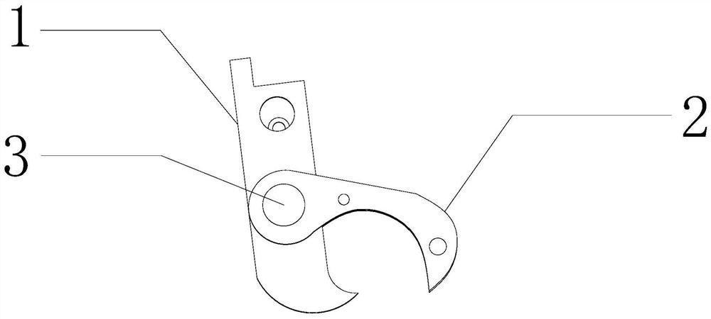
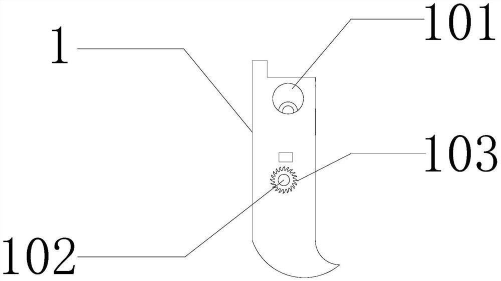
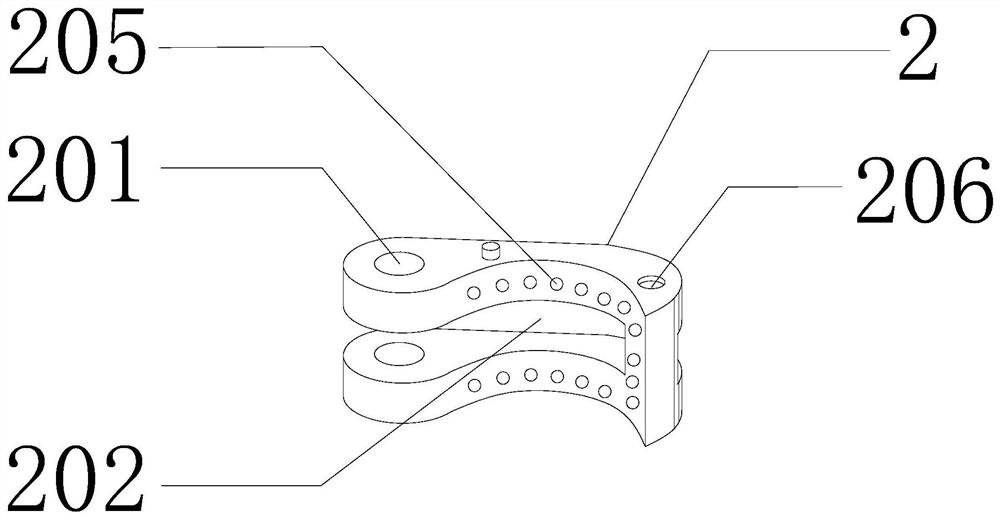
[0033] see Figure 1-Figure 4, a self-locking device for hoisting a cable reel, comprising: a first self-locking block 1, a second self-locking block 2 and a stop pin 3, the upper end of the first self-locking block 1 is in an "L" shape, and the lock is on the first self-locking block. When hoisting on the lock block 1, you can rely on the "L" shape to better apply force to the device. The lower end is in the shape of a "crescent" hook. The pressure of the lo...


PUM


Abstract

The invention relates to the field of self-locking devices, and discloses a self-locking device for hoisting a cable reel. The self-locking device comprises a first self-locking block, a second self-locking block and a stop pin, wherein the first self-locking block is provided with a hoisting hole, a first through hole and a gear, and a fastening component is arranged inside the first self-lockingblock; one side of the second self-locking block is S-shaped, and a second through hole, a first clamping groove and a check component are arranged on the second self-locking block; the clamping groove transversely penetrates through part of the second self-locking block; the first self-locking block is arranged in the first clamping groove; the stop pin comprises a stop pin shaft and two stop pieces; the stop pieces are fixedly arranged at two ends of the pin shaft and arranged in the first through hole and the second through hole; and the stop pieces are fixedly connected with the second self-locking block. A self-locking function of the self-locking device is achieved through the cooperation of the first self-locking block, and the self-locking force increases along with the increase of hoisting weight, so that hoisting is firmer; the hoisting process of the cable reel is safer and more reliable by arranging the fastening component and the check component; and the self-locking device has novelty and creativity, and improves the practicability.

Description

technical field [0001] The invention relates to the field of self-locking devices, in particular to a self-locking device for hoisting cable reels. Background technique [0002] In the cable industry, it is necessary to hoist the cable reel on the reel, and the traditional hoisting method often uses a wire rope or a hoisting belt to bind the cable reel first, and then hoist it. If the binding method is wrong, safety accidents are very likely to occur. Inquire: [0003] A proposed cable reel lifting device (publication number CN107512658A) includes a slider hole and a trunnion at the upper and lower ends of the lifting lug, and a driving inner nut and a locking screw on the lower side of the slider hole and one side. , the two ends of the front and back buckle screw are respectively supported by the lower part of the side support beam, and the two ends are set in the drive inner nut of the lifting lug. The outside of the side support beam is equipped with a DC motor connecte...

Claims


Application Information

Patent Timeline
Patent Type & Authority Applications(China)
IPC IPC(8): B66C1/12B66C1/02B66C1/48
CPCB66C1/12B66C1/025B66C1/48
Inventor 顾正扬王荣张炳楼
Owner 浙江龙鹰光电科技有限公司
Why Eureka
Try Eureka