A driving mast of a steel cage roll welding machine

A technology of rolling welding machine and steel cage, which is applied in the direction of roller electrode welding, welding equipment, resistance welding equipment, etc., can solve the problems of cumbersome and time-consuming installation process and the impact of steel cage production work, and achieve stable, powerful, stable and efficient functions. The effect of positioning

Active Publication Date: 2021-12-03
新昌县雷涛机械有限公司
View PDF0 Cites 0 Cited by
  • Summary
  • Abstract
  • Description
  • Claims
  • Application Information

AI Technical Summary

Problems solved by technology

[0002] In the prior art, a number of steel bar end fixing unit components are installed on the drive gantry of the seam welding machine, and the steel bars are fixed on the unit components one by one manually, requiring additional tools. affect

Method used


Image

  • A driving mast of a steel cage roll welding machine
  • A driving mast of a steel cage roll welding machine
  • A driving mast of a steel cage roll welding machine

Examples


Embodiment Construction

[0018] The following will clearly and completely describe the technical solutions in the embodiments of the present invention with reference to the accompanying drawings in the embodiments of the present invention. Obviously, the described embodiments are only some, not all, embodiments of the present invention. Based on the technical solutions in the present invention, all other embodiments obtained by persons of ordinary skill in the art without making creative efforts belong to the protection scope of the present invention.

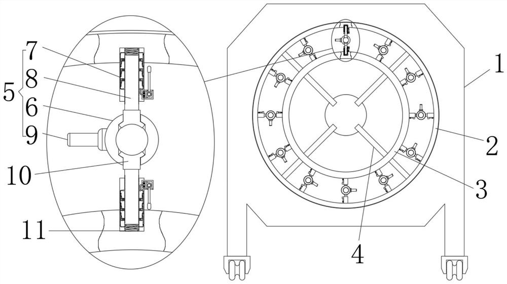
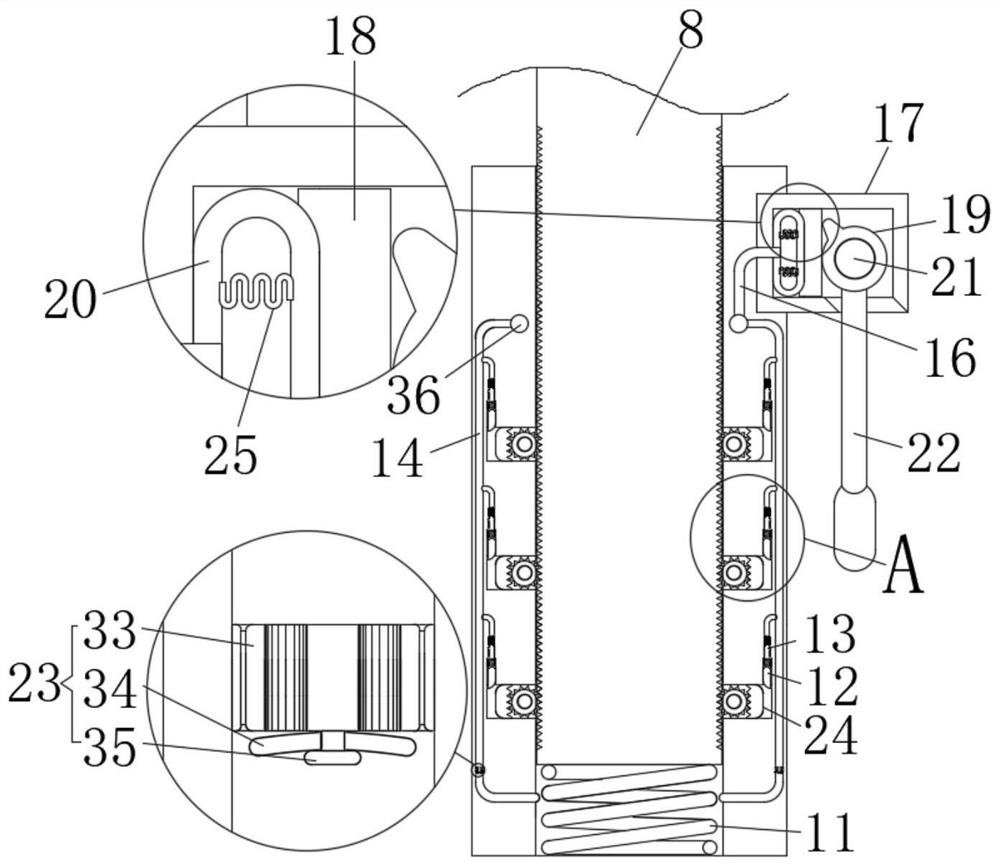
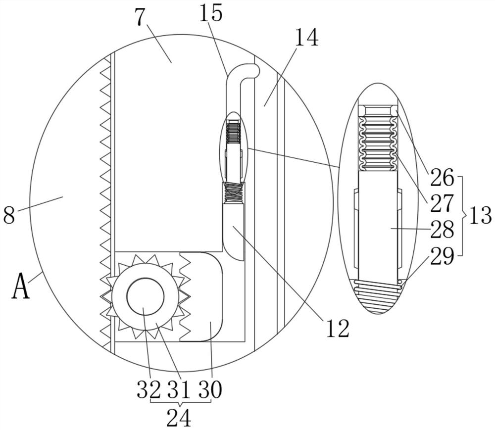
[0019] see Figure 1 to Figure 3 , the present invention provides a technical solution: a driving gantry of a steel bar cage roll welding machine, including a gantry 1, a round hole is opened on the gantry 1, an outer ring 2 is set in the round hole of the gantry 1, and the outer ring 2 is covered with an inner ring 3, a support rod 4 is fixedly connected between the outer ring 2 and the inner ring 3, and a number of evenly distributed clamping devices...


PUM


Abstract

The invention relates to the technical field of driving gantry for roll welding machines, in particular to a driving gantry for steel cage roll welding machines, including a door frame with a round hole on the door frame, and an outer ring in the round hole of the door frame. There is an inner ring in the ring, and a support rod is fixedly connected between the outer ring and the inner ring. There are several evenly distributed clamping devices on the ring between the outer ring and the inner ring. The clamping device includes an outer cylinder, a positioning cylinder, and a telescopic column. And the side rod, the structure design of the present invention realizes the stable and efficient positioning effect of the outer cylinder. It only needs to manually reciprocate the pressure rod to break the clamping state between the positioning cylinder and the telescopic column in a short time, and then manually move it The position of the side lever and then the outer cylinder is adjusted, and the outer cylinder is automatically and firmly positioned after a certain period of time, with stable and powerful functions.

Description

technical field [0001] The invention relates to the technical field of a drive door frame of a roll welding machine, in particular to a drive door frame of a steel cage roll welder. Background technique [0002] In the prior art, a number of steel bar end fixing unit components are installed on the drive gantry of the seam welding machine, and the steel bars are fixed on the unit components one by one manually, requiring additional tools. affect. [0003] If a steel bar clamping device can be invented on the drive door frame of the roll welding machine, the end of the steel bar can be fixed on the clamping device conveniently and quickly, and the problem can be solved. For this reason, we provide a steel bar cage roll welding machine drive mast. Contents of the invention [0004] The object of the present invention is to provide a driving mast of a steel cage seam welder to solve the problems raised in the above-mentioned background technology. [0005] In order to achi...

Claims


Application Information

Patent Timeline
Patent Type & Authority Patents(China)
IPC IPC(8): B23K11/06B23K11/36B21F15/02
CPCB21F15/02B23K11/06B23K11/36
Inventor 竹洪燕
Owner 新昌县雷涛机械有限公司
Why Eureka
Try Eureka