On-load replacement protection device for drop-out fuse and electrified replacement method of on-load replacement protection device

A technology of drop-out fuses and protection devices, which is applied in the direction of overhead lines/cable equipment, etc., can solve problems such as live working hazards, arc discharge, safety hazards, etc., and achieve the effect of live working

Active Publication Date: 2020-11-03
STATE GRID TIANJIN ELECTRIC POWER +1
View PDF6 Cites 0 Cited by
  • Summary
  • Abstract
  • Description
  • Claims
  • Application Information

AI Technical Summary

Problems solved by technology

In the power distribution system, it often occurs that the drop-out fuse needs to be replaced with power when it fails. Because the safety distance of the work site itself is very small when the drop-out fuse is replaced with load, and the insurance of the drop-out fuse is replaced In the process of falling off and falling to the ground, arcing phenomenon occurs, which will easily bring great safety hazards to live operators in the bucket and great danger to ground electrician cooperating with live work, which is prone to personal accidents
In the traditional mode, the replacement of the drop-out fuse with load requires a bypass connection between the main line and the lower lead of the drop-out fuse, and the traditional bypass drain line cannot be applied to various work sites. The distance between the drop-out fuses is small, and the traditional bypass There is no fixed device for the drainage line, it is easy to swing, without any protective measures, it is prone to accidents

Method used


Image

  • On-load replacement protection device for drop-out fuse and electrified replacement method of on-load replacement protection device
  • On-load replacement protection device for drop-out fuse and electrified replacement method of on-load replacement protection device
  • On-load replacement protection device for drop-out fuse and electrified replacement method of on-load replacement protection device

Examples


Embodiment Construction

[0029] Below in conjunction with the examples, the present invention is further described, the following examples are illustrative, not limiting, and the protection scope of the present invention cannot be limited by the following examples.

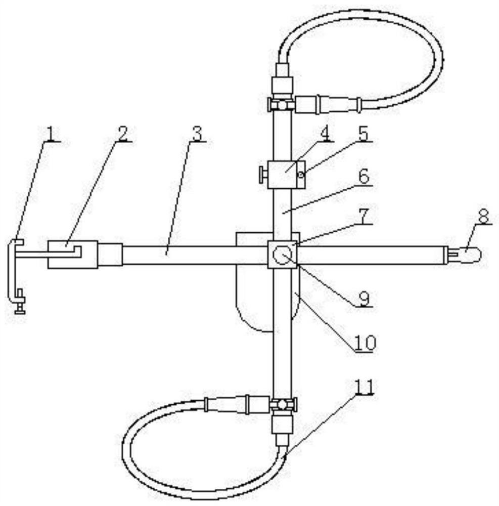
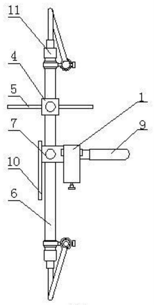
[0030] An on-load replacement protection device for a drop-out fuse. The innovation of the present invention is that it includes a connecting block 7. The connecting block is in the shape of a cube, and through holes are respectively made in the inside along the longitudinal and transverse directions. Each through hole is An insulating sleeve is installed, and the two insulating sleeves are arranged perpendicular to each other in a "ten" structure. Among them, the horizontal bar 3 is arranged along the horizontal direction, and the longitudinal bar 6 is arranged along the longitudinal direction. Under the action of the connecting block, the horizontal bar and the vertical bar can be driven. The longitudinal bar slides relative to each othe...


PUM


Abstract

The invention belongs to the field of hot-line work devices, and relates to an auxiliary device for replacement of a drop-out fuse, in particular to an on-load replacement protection device for the drop-out fuse. The device comprises a connecting block, the connecting block is cubic, through holes are respectively formed in the connecting block in the longitudinal direction and the transverse direction, an insulating sleeve is arranged in each through hole in a penetrating manner, and the insulating sleeves are connected with the connecting block. The two insulating sleeves are perpendicular to each other and are distributed in a cross-shaped structure, the transverse rod is arranged in the transverse direction, the longitudinal rod is arranged in the longitudinal direction, the transverserod and the longitudinal rod can be driven to slide relatively under the action of the connecting block, a clamping block is installed at the end of one side of the transverse rod, and the clamping block is used for being clamped with a cross arm where the drop-out fuse is installed. A flexible cable is installed in the longitudinal rod in a penetrating mode, the two ends of the flexible cable extend out of the two ends of the longitudinal rod respectively, and the two ends of the flexible cable are used for being connected and conducted with an upper lead and a lower lead of the drop-out fuse respectively.

Description

technical field [0001] The invention belongs to the field of live working devices, and relates to an auxiliary device for replacing a drop-out fuse, in particular to an on-load replacement protection device for a drop-out fuse and a live replacement method thereof. Background technique [0002] As the pace of urbanization continues to accelerate, the maintenance practice of "one line is pulled, one stop is a large area" of power grid enterprises can no longer meet the electricity demand of the society. In order to create a good business environment and fully improve the reliability of power supply, in this Under such circumstances, uninterrupted operation has become a magic weapon to maintain the reliability of power supply, so "live work" has become the most direct way to reduce user power outages and the most effective measure to improve power supply reliability. In the power distribution system, it often occurs that the drop-out fuse needs to be replaced with power when i...

Claims


Application Information

Patent Timeline
Patent Type & Authority Applications(China)
IPC IPC(8): H02G1/02
CPCH02G1/02
Inventor 张冰刘洪双高立宝
Owner STATE GRID TIANJIN ELECTRIC POWER
Why Eureka
Try Eureka