
Drying device for agricultural machinery

A drying device and agricultural machinery technology, applied in the agricultural field, can solve the problems of general drying effect and the like

Inactive Publication Date: 2020-11-03
周同永
View PDF1 Cites 1 Cited by
  • Summary
  • Abstract
  • Description
  • Claims
  • Application Information

AI Technical Summary

Problems solved by technology

But the drying effect of this device is average, so the device needs to be improved

Method used


Image

  • Drying device for agricultural machinery
  • Drying device for agricultural machinery
  • Drying device for agricultural machinery

Examples


Embodiment 1

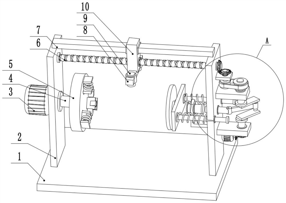
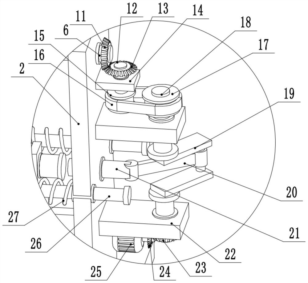
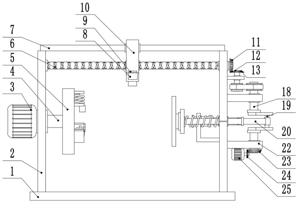
[0027] see Figure 1-5 , a drying device for agricultural machinery, comprising a base plate 1, side plates 2 are provided on the left and right sides of the upper surface of the base plate 1, the middle part of the side plate 2 on the left side is connected to the first rotating shaft 4 in rotation, and the side plate on the left side The middle part of 2 is provided with the first drive motor 3, and the output shaft of the first drive motor 3 is fixedly connected with the left end of the first rotating shaft 4, and the right end of the first rotating shaft 4 is provided with the clamping seat 5, and the upper and lower sides of the side plate 2 on the right side A second fixed plate 22 is provided, the right side of the second fixed plate 22 is rotatably connected to the second rotating shaft 18, the bottom of the second fixed plate 22 on the lower side is provided with a second drive motor 25, and the output shaft of the second drive motor 25 The first bevel gear 24 is fixe...

Embodiment 2

[0030] see Figure 5 , the other content of this embodiment is the same as that of Embodiment 1, except that: the left end of the first rotating shaft 4 is fixedly connected to the running wheel 33 . The rotation of the rotating shaft is controlled by setting the rotating wheel 33 on the left side of the rotating shaft, thereby controlling the rotation of the clamping seat 5. In this way, one driving unit of the device can be reduced, and the manual operation is more flexible.

[0031]During the implementation of the present invention, the top plate 31 is pushed to the right, and the agricultural machinery that needs to be dried is fixed on the clamping seat 5. At this time, the top plate 31 is released, and under the action of the spring 27, the top plate 31 moves to the left. , so that the agricultural machinery is clamped by the top plate 31 and the clamping seat 5. At this time, the hot blower 9 is started, and the first drive motor 3 and the second drive motor 25 are star...


PUM


Abstract

The invention relates to the technical field of agriculture, and discloses a drying device for agricultural machinery. The device comprises a bottom plate, side plates are arranged on the left side and the right side of the upper surface of the bottom plate, a first rotating shaft is rotatably connected to the middle of the side plate on the left side, a clamping seat is arranged at the right endof the first rotating shaft, and second fixing plates are arranged above and below the side plate on the right side. A second rotating shaft is rotatably connected to the right sides of one second fixing plate, a crank is arranged in the middle of the second rotating shaft, the middle of the crank is rotationally connected with the right end of a supporting rod, the left end of the supporting rodis rotationally connected with a sliding rod, the front side and the rear side of the side plate on the right side are slidably connected with guide rods, and a third fixing plate is arranged at the left ends of the guide rods; and the left side of the third fixing plate is rotationally connected with an ejecting plate. The drying device suitable for the agricultural machinery is further providedwith an impact head capable of rapidly moving left and right, the agricultural machinery is continuously impacted through the impact head, the agricultural machinery vibrates, water stains attached tothe surface of the agricultural machinery are rapidly shaken off, and therefore the drying effect is improved.

Description

technical field [0001] The invention relates to the field of agricultural technology, in particular to a drying device for agricultural machinery. Background technique [0002] Agricultural machinery refers to various machinery used in crop planting and animal husbandry production, as well as in the primary processing and handling of agricultural and animal products. Agricultural machinery includes agricultural power machinery, farmland construction machinery, soil tillage machinery, planting and fertilization machinery, plant protection machinery, farmland drainage and irrigation machinery, crop harvesting machinery, agricultural product processing machinery, animal husbandry machinery and agricultural transportation machinery, etc. The surface of agricultural machinery will be stained with water when it is in use. However, the anti-rust ability of some key parts is not good. In order to prevent rust during storage, it is necessary to dry the agricultural machinery. [000...

Claims


Application Information

Patent Timeline
IPC IPC(8): F26B11/00F26B21/00F26B21/06F26B25/00
CPCF26B11/00F26B21/001F26B21/06F26B25/00
Inventor 周同永
Owner 周同永
Learn More