Actuator of a nuclear reactor control and protection system

A technology of actuating mechanism and protection system, applied in the field of actuating mechanism of a system for controlling and protecting a nuclear reactor, can solve problems such as rod and working part bayonet connection and disconnection, stopper failure and the like

Active Publication Date: 2020-10-30
ROSSIJSKAJA FEDERATSIJA OT IMENI KOTOROJ VYSTUPAET GOSUDARSTVENNAJA KORPORATSIJA PO ATOMNOJ EHNERGII ROSATOM
View PDF7 Cites 0 Cited by
  • Summary
  • Abstract
  • Description
  • Claims
  • Application Information

AI Technical Summary

Problems solved by technology

[0004] A disadvantage of the known drive mechanisms for nuclear reactor control and protection systems is that the bayonet connection of the rod and the working part may be spontaneous due to the failure of the spring-loaded stop due to the intense radiation and high temperature in the lower end region of the rod disengage

Method used


Image

  • Actuator of a nuclear reactor control and protection system
  • Actuator of a nuclear reactor control and protection system
  • Actuator of a nuclear reactor control and protection system

Examples


Embodiment Construction

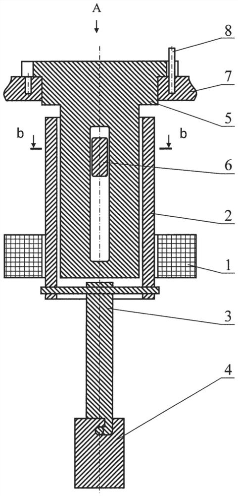
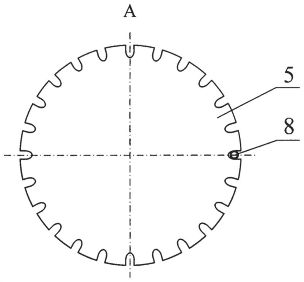
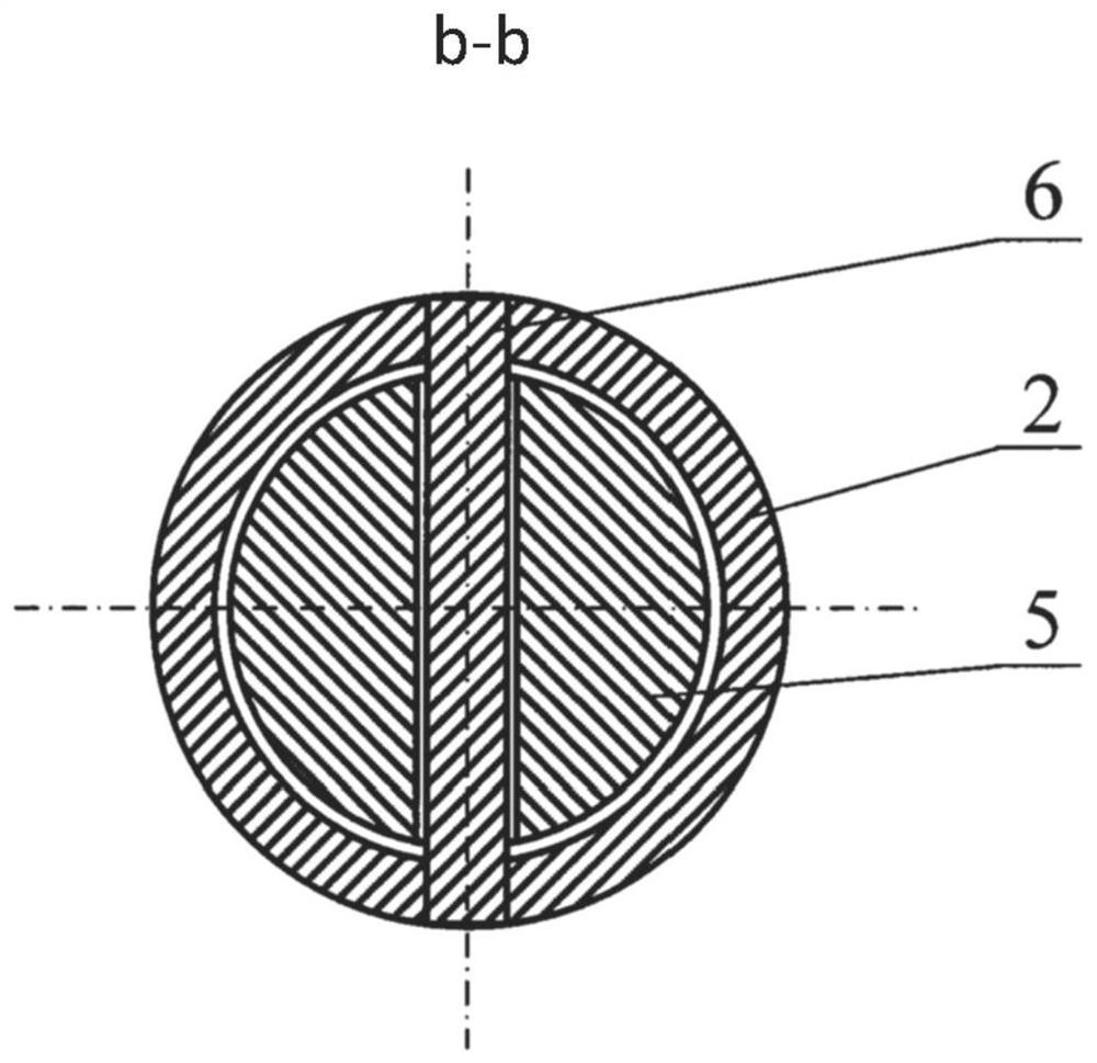
[0013] The actuation mechanism of the nuclear reactor control and protection system consists of: a linear stepper motor 1 with an armature (anchor) 2 in the form of a vertical tube; a rod 3 mounted coaxially with the armature 2 and rigidly connected to the armature, to allow joint / joint vertical displacement and rotation around a common vertical axis; and a lock preventing spontaneous rotation of the rod 3 . The lower end of the rod 3 is connected to the working part 4 by an L-shaped bayonet joint. The locking piece preventing the spontaneous rotation of the rod has a guide part 5 , a transverse piece 6 , a fixed (immovable) ring 7 and a vertical pin 8 . The guide portion 5 is provided with a flange at its upper end. The lower part of the guide 5 is located inside the armature 2 . The inner surface of the flange of the guide rests on the fixing ring 7 and is centered about its inner circumference. In the free lower part of the guide 5 there is a longitudinal through-slot in...


PUM


Abstract

The invention relates to the field of nuclear engineering and can be used in nuclear reactor control and protection system actuators. An actuator of a nuclear rector control and protection system comprises: a linear stepper motor having an armature; a rod which is arranged coaxially with the armature, and which is rigidly connected to the armature to provide vertical movement and rotation about avertical axis, and which is designed to be capable of forming an L-shaped bayonet connection with a working member; and a lock to prevent spontaneous rotation of the rod. The lock comprises a guide which is arranged inside the armature and which is provided with a flange and a longitudinal through slot; a cross-member which is rigidly connected to the armature and which is mounted in the slot suchas to be capable of vertical movement therein during a working stroke; a fixed ring, on which the inside surface of the flange rests; and a vertical pin. Through slots are arranged equidistantly on the outside rim of the flange, and openings are arranged equidistantly about the circumference of the fixed ring, the vertical pin being mounted in one of said openings such as to pass through one of the through slots in the flange. The technical result of the present invention is that of preventing spontaneous disengagement of the bayonet connection, while also reducing the number of steps required to engage and disengage said connection.

Description

technical field [0001] The invention relates to the field of nuclear technology and can be used for an actuating mechanism of a nuclear reactor control and protection system. Background technique [0002] Most relevant to all essential features of the invention is an actuation mechanism for a nuclear reactor control and protection system having: a linear stepper motor with an armature (anchor); coaxial with the armature a lever arranged and rigidly connected to the armature to allow combined / joint vertical displacement and rotation about a vertical axis, the lever being manufactured to form a bayonet joint with the working part; and a lock preventing the lever from turning spontaneously (with Fundamentals of Construction of Actuating Mechanisms for Nuclear Reactor Control (Ru.); I.Ya. Yemelyanov, V.V. Voskoboinikov, B.A. Maslenok; M.: Energoatomizdat, 1987; image 3 .15b, page 41). [0003] In known actuation mechanisms for systems for controlling and protecting nuclear rea...

Claims


Application Information

Patent Timeline
Patent Type & Authority Applications(China)
IPC IPC(8): G21C7/14
CPCG21C7/10G21C7/14Y02E30/30
Inventor M·Y·库德雷亚夫采夫
Owner ROSSIJSKAJA FEDERATSIJA OT IMENI KOTOROJ VYSTUPAET GOSUDARSTVENNAJA KORPORATSIJA PO ATOMNOJ EHNERGII ROSATOM
Why Eureka
Try Eureka