Water treatment and air source heat pump detection display system

An air source heat pump and display system technology, applied in the direction of data processing power supply, signal transmission system, electrical digital data processing, etc., can solve unresolved detection signals, unadjusted module clarity, or other various data and signal inconsistencies deal with issues

Pending Publication Date: 2020-10-30
江苏中广泳池科技有限公司
View PDF7 Cites 1 Cited by
  • Summary
  • Abstract
  • Description
  • Claims
  • Application Information

AI Technical Summary

Problems solved by technology

[0003] Such as the display system disclosed by the authorized announcement number CN1906570A, although it provides a computer with a storage capacity larger than the display, it will be more convenient for the user to operate the computer, which strengthens the user's control over the image display state, and can provide the user with the ability to adjust the image display. Friendly graphical interface, but it does not solve the problem that the existing detection and display system cannot transmit the detection signal through wireless transmission, the signal after transmission is not processed, and there is no adjustment module to adjust the clarity of the image or other Various data; the power supply module and driver on the control module are simple and inconvenient to use, and the data displayed on the display screen cannot be stored and recorded. Therefore, we propose a water treatment and air source heat pump detection and display system

Method used


Image

  • Water treatment and air source heat pump detection display system
  • Water treatment and air source heat pump detection display system
  • Water treatment and air source heat pump detection display system

Examples


Embodiment Construction

[0026] The following will clearly and completely describe the technical solutions in the embodiments of the present invention with reference to the accompanying drawings in the embodiments of the present invention. Obviously, the described embodiments are only some, not all, embodiments of the present invention. Based on the embodiments of the present invention, all other embodiments obtained by persons of ordinary skill in the art without making creative efforts belong to the protection scope of the present invention.

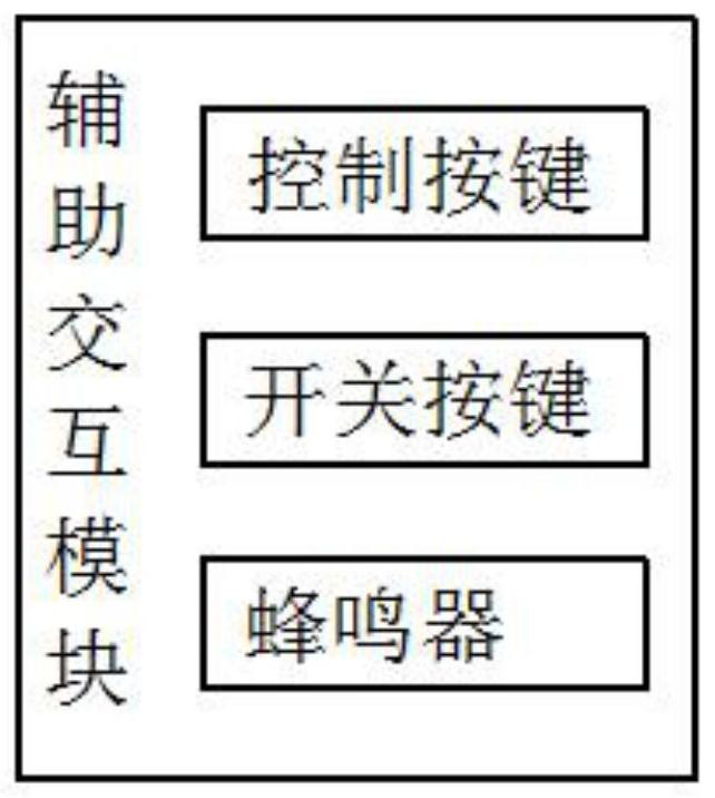
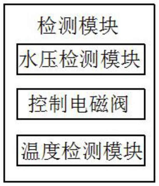
[0027] see Figure 1-Figure 5 , the present invention provides a technical solution: a water treatment and air source heat pump detection and display system, including a control module, the control module is electrically connected with a power supply, a wireless receiving module, a storage module, an auxiliary interactive module and an LED display screen, the wireless receiving module is connected to a wireless sending module through wireless transmission, the...


PUM


Abstract

The invention discloses a water treatment and air source heat pump detection display system. The water treatment and air source heat pump detection display system includes a control module, the control module is electrically connected with a power supply, a wireless receiving module, a storage module, an auxiliary interaction module and an LED display screen. The wireless receiving module is connected with a wireless sending module through wireless transmission, the wireless sending module is electrically connected with a detection module, and the control module internally comprises a receiving unit, an image processing module, an adjusting module, a driving module and a flash memory unit. According to the invention, signal transmission is carried out through wireless transmission, signalsare progressively transmitted to the image processing module through the receiving unit, and the adjusting module is used for adjusting the definition of images or other various data; the air sourceheat pump is detected through the detection module, the power supply module is arranged so that the voltage can adapt to the control module for use, the flash memory and the storage module are arranged so that data displayed by the display screen can be stored and recorded, and data loss is prevented.

Description

technical field [0001] The invention belongs to the technical field of detection and display systems, and in particular relates to a detection and display system for water treatment and air source heat pumps. Background technique [0002] An electronic system that provides visual information. According to different applications, the display system uses one or more, one or more display devices, provides visual information required by a single person or a group of people, and receives signals from different electronic devices or systems. Generally, it needs to be equipped with appropriate The input device is used to realize the human-machine connection and the necessary recording equipment for later reference. There are many types of information display systems, and there are many classification methods. According to the displayed content, there are generally three categories: characters, graphics and situation displays; According to the display devices used, it can be divide...

Claims


Application Information

Patent Timeline
IPC IPC(8): G06F3/14G08C17/02G01D21/02G06F1/26G11B31/00
CPCG06F3/1407G08C17/02G01D21/02G06F1/266G11B31/00
Inventor 谈云飞
Owner 江苏中广泳池科技有限公司
Why Eureka
Try Eureka