Layered medium resistivity anisotropy ocean controllable source electromagnetic rapid inversion method
A technology of anisotropy and medium resistance, applied in the field of rapid electromagnetic inversion of layered medium resistivity anisotropy in the ocean, can solve the problems of slow inversion speed and low efficiency, and achieve high efficiency and high inversion speed. fast effect
- Summary
- Abstract
- Description
- Claims
- Application Information
AI Technical Summary
Problems solved by technology
Method used
Image
Examples
Embodiment 1
[0048]The invention provides a controllable-source electromagnetic fast inversion method for layered medium resistivity anisotropy. Compared with the traditional inversion algorithm, the algorithm proposed by the invention has the characteristics of fast inversion speed, high efficiency and strong adaptability. At the same time, the inversion method provides a feasible technical means for testing data quality in the field and quickly obtaining inversion interpretation results.
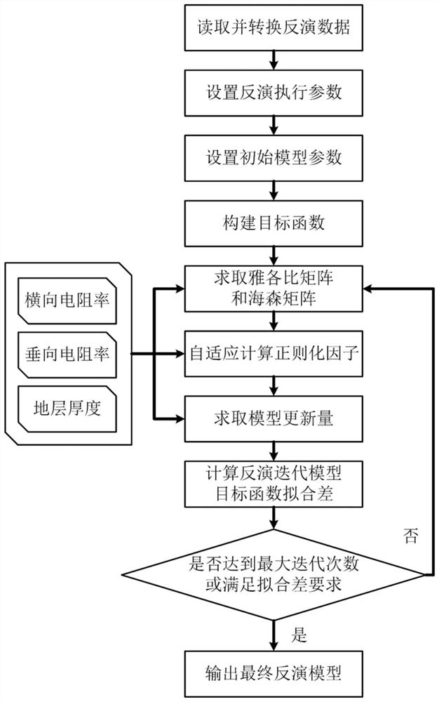
[0049] see figure 1 , a controllable source electromagnetic fast inversion method for layered medium resistivity anisotropy, which mainly includes the following steps:
[0050] S1. Read and convert the ocean controllable source electromagnetic field data involved in the inversion, the data includes electromagnetic field real and imaginary part data, amplitude and phase data, and parameters of the major axis and minor axis of the polarization ellipse.
[0051] According to the user's requirements, th...
Embodiment 2
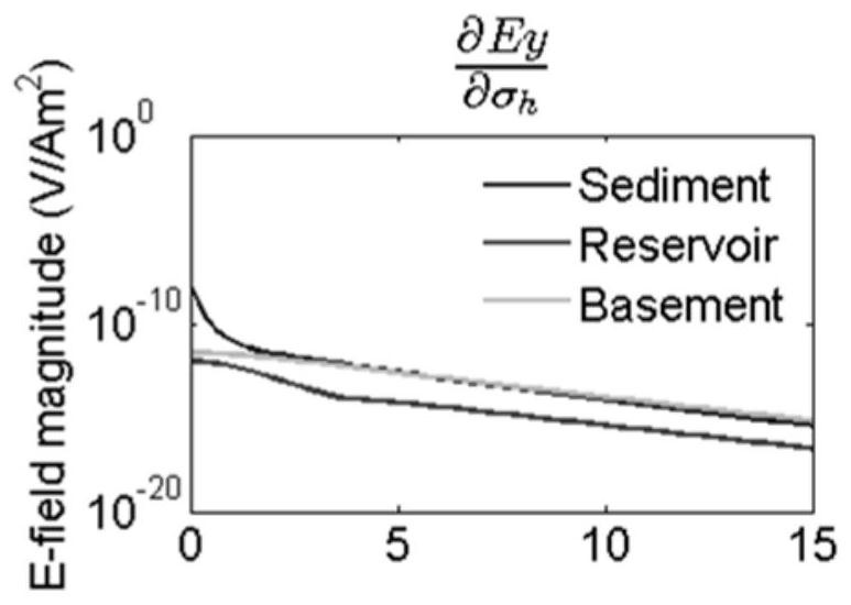
[0103] In order to verify the correctness of the sensitivity matrix, refer to figure 2 , is a schematic diagram of a typical one-dimensional geoelectric model, assuming that the depth of the resistivity isotropic seawater layer is 10km, and the resistivity is 0.3Ωm. The buried depth of the isotropic high-resistivity thin layer with a thickness of 100m is 1km, and the resistivity is ρ=40Ωm. The resistivity of overburden and bedrock is also isotropic formation, and the resistivities of overburden and bedrock are ρ=2Ωm and ρ=4Ωm, respectively. Assuming that the survey line coincides with the y-axis, 76 transmitters are arranged at equal intervals within the range of 0m-15000m from the survey line, and are all located 50m above the seabed, the transmission frequency is 0.25Hz, the receiving station is located on the seabed, and the coordinates are (x =0m, y=0m, z=10000m). by figure 2 The one-dimensional resistivity isotropy model shown is taken as an example to verify the cor...
Embodiment 3
[0108] This embodiment is the inversion of the resistivity isotropic half-space model. Since there is no subsurface stratification in the half-space model, the influence of formation thickness on the inversion can be removed. Two half-space models are established, assuming that the seabed half-space is an isotropic resistivity medium, and the resistivities are 2Ωm and 40Ωm, respectively. In real geophysical inversion, it is often unknown how many layers of media there are on the seabed, and the number of stratum layers is usually set to be more than the number of real stratum layers. Therefore, the seabed of the initial inversion model is set to 5 layers, and the resistivity and layer thickness of the seabed medium strata (resistivity isotropic inversion), as well as the lateral resistivity, vertical resistivity and layer thickness (resistivity Anisotropic inversion) for inversion.
[0109] In axial viewing mode, a y-oriented horizontal electric dipole source produces a hori...
PUM
 Abstract
Description
Claims
Application Information
 - R&D
- Intellectual Property
- Life Sciences
- Materials
- Tech Scout
- Unparalleled Data Quality
- Higher Quality Content
- 60% Fewer Hallucinations
Browse by: Latest US Patents, China's latest patents, Technical Efficacy Thesaurus, Application Domain, Technology Topic, Popular Technical Reports.
© 2025 PatSnap. All rights reserved.Legal|Privacy policy|Modern Slavery Act Transparency Statement|Sitemap|About US| Contact US: help@patsnap.com


