Geosynthetic material direct tensile/pull-out tester and test method
A geosynthetic material, pull test technology, applied in the analysis of materials, the use of stable tension / pressure test material strength, instruments and other directions, can solve the problems of multiple errors, split tensile strength is not easy to operate, etc., to improve the accuracy performance, and the effect of improving utilization
- Summary
- Abstract
- Description
- Claims
- Application Information
AI Technical Summary
Problems solved by technology
Method used
Image

Examples
Embodiment 1
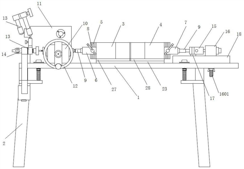
[0075] The present invention specifically provides a geosynthetics straight-pull tester, which includes a workbench composed of a horizontal plate 1 and support legs 2, and is characterized in that it also includes a driving device, a pulling device, and a displacement measuring device arranged on the workbench. device, tension measuring device and data collector.
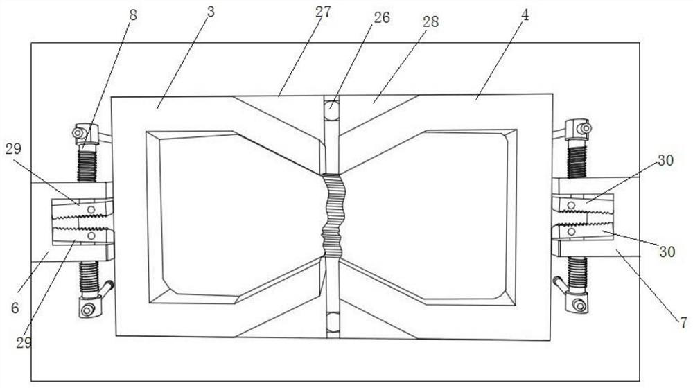
[0076] refer to figure 1 and 6 As shown, specifically, the drawing device includes a mounting plate 23 arranged on the workbench, two long sides of the mounting plate 23 are provided with symmetrical chute 2301, and the chute 2301 is provided with Strip plate 24, described strip plate 24 is provided with a plurality of equally spaced through holes, and described through hole communicates with chute 2301, all is provided with ball 26 in each through hole, in strip plate 24 A left slide plate 27 and a right slide plate 28 are arranged on the top, and the upper ends of the left slide plate 27 and the right slide pla...
Embodiment 2
[0095] The present invention also provides a pull-out tester for geosynthetics, which includes a workbench composed of a horizontal plate 1 and support legs 2, and is characterized in that it also includes a driving device, a pullout device, and a displacement measuring device arranged on the workbench. device, tension measuring device and data collector.
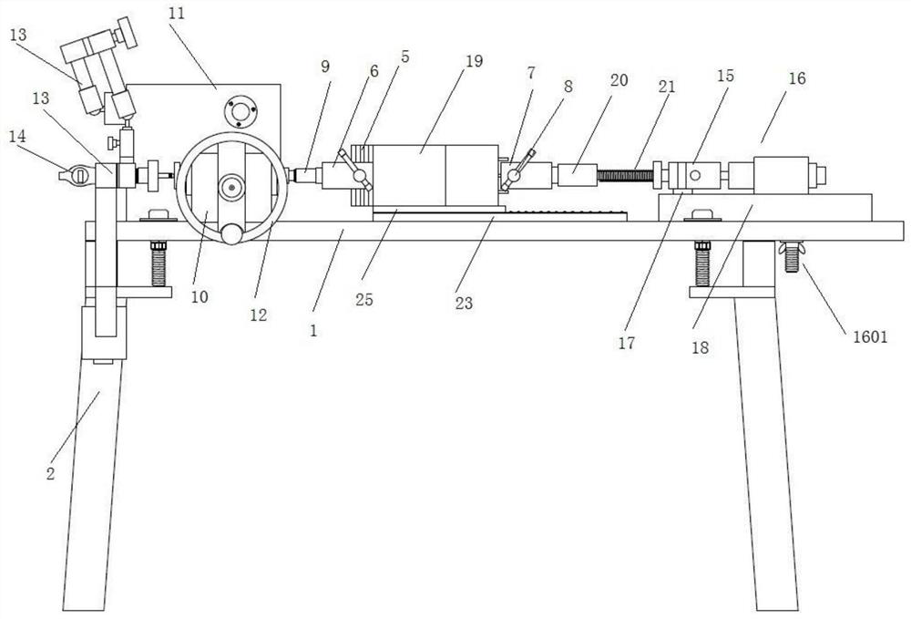
[0096] refer to image 3 As shown, specifically, the drawing device includes a mounting plate 23 arranged on the workbench, two long sides of the mounting plate 23 are provided with symmetrical chute 2301, and the chute 2301 is provided with Strip plate 24, described strip plate 24 is provided with a plurality of equally spaced through holes, and described through hole communicates with chute 2301, all is provided with ball 26 in each through hole, in strip plate 24 Sliding plate 25 is arranged on it, and the bottom of described sliding plate 25 is slidably connected with ball 26, and the upper end of described sliding pla...
Embodiment 3
[0116] The difference from Example 2 is that the exposed fiber of the sample in this example is clamped in the chuck 2201 at the rear end of the connecting rod 22 and fixed by the fixing screw 2202, and the front end of the connecting rod 22 is connected to the force sensor 15. This embodiment is applicable to a single fiber pulling test.
[0117] The fixed block on the right side of the original direct shear instrument is designed to be non-adjustable up, down, left, and right, which is not conducive to the alignment of the pull-out test and the straight-pull test. Especially for the pull-out test, the heights of the three layers of fibers are different, so it is transformed into a Mechanism that can be adjusted up and down. For the centering problem, it is divided into left and right centering and up and down centering. Left and right centering is solved by adjusting the relative position of the clamping structure on the left and right of the clamp head (such as Figure 5 A...
PUM
| Property | Measurement | Unit |
|---|---|---|
| particle size | aaaaa | aaaaa |
Abstract
Description
Claims
Application Information
 - Generate Ideas
- Intellectual Property
- Life Sciences
- Materials
- Tech Scout
- Unparalleled Data Quality
- Higher Quality Content
- 60% Fewer Hallucinations
Browse by: Latest US Patents, China's latest patents, Technical Efficacy Thesaurus, Application Domain, Technology Topic, Popular Technical Reports.
© 2025 PatSnap. All rights reserved.Legal|Privacy policy|Modern Slavery Act Transparency Statement|Sitemap|About US| Contact US: help@patsnap.com