Spiral-flow type underground liquid-gas separation device

A technology of liquid-gas separation and cyclone separator, which is applied in the direction of gas fuel, petroleum industry, fuel, etc., and can solve the problems of reducing pour point depressing, thickening efficiency, affecting oil well production, increasing pour point depressing, etc.

Pending Publication Date: 2020-10-30
鞍山宏景石油机械有限公司 +1
View PDF0 Cites 0 Cited by
  • Summary
  • Abstract
  • Description
  • Claims
  • Application Information

AI Technical Summary

Problems solved by technology

This not only increases the cost of pour point and thickening, but also reduces the...

Method used


Image

  • Spiral-flow type underground liquid-gas separation device
  • Spiral-flow type underground liquid-gas separation device
  • Spiral-flow type underground liquid-gas separation device

Examples


Embodiment Construction

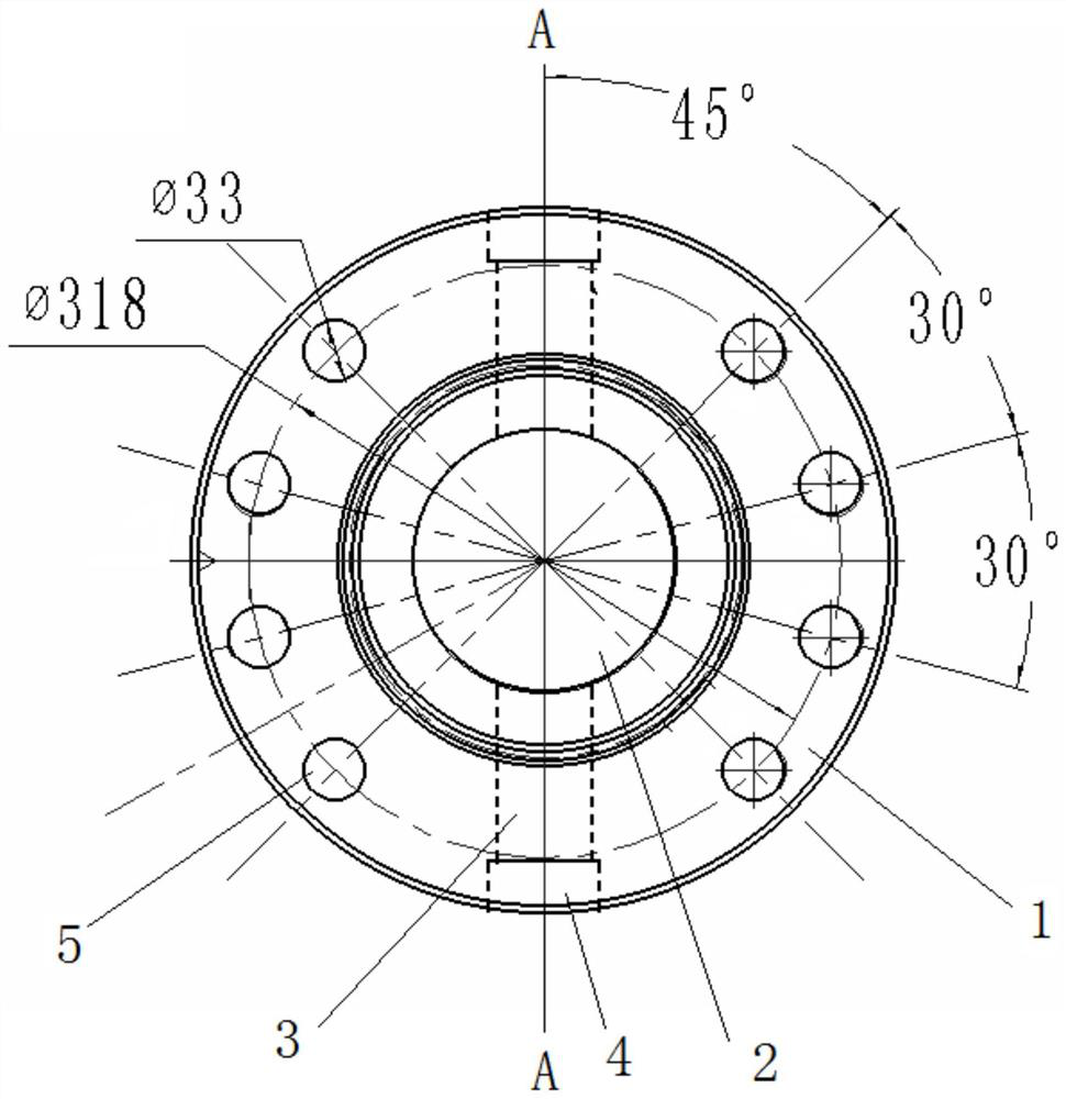
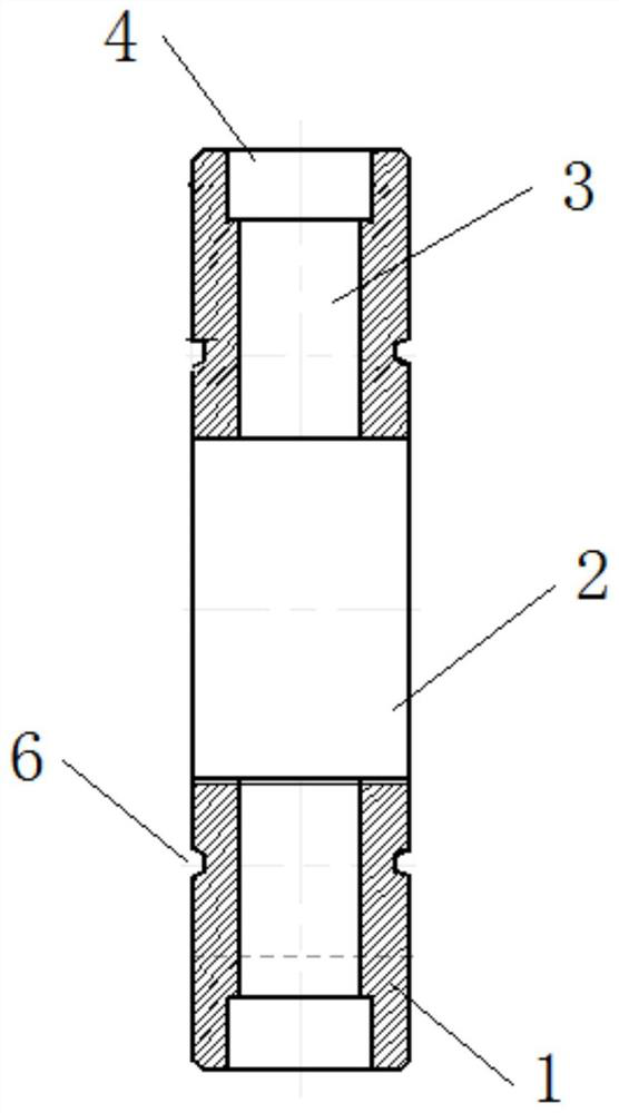
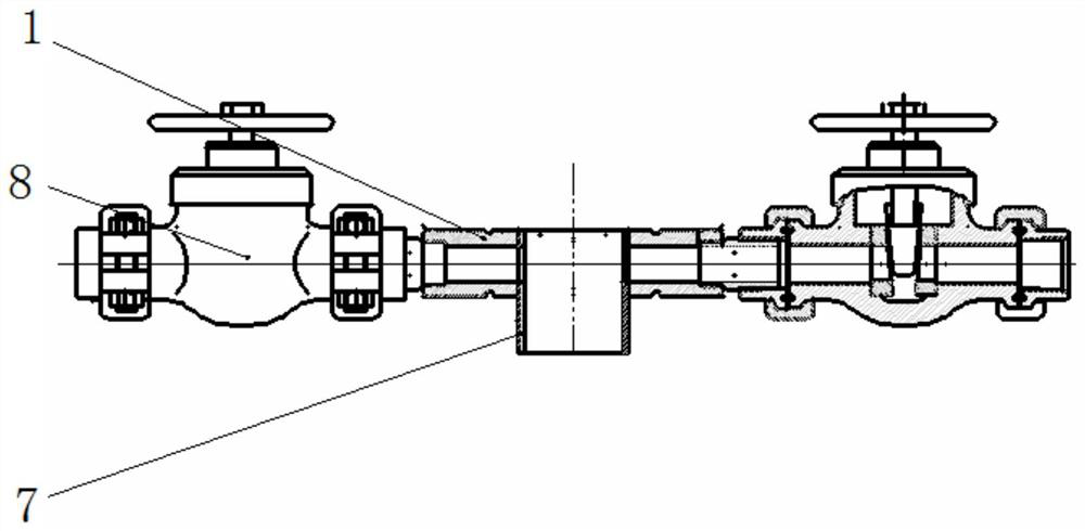
[0020] like Figure 1-7 As shown, a swirl-type downhole liquid-gas separation device includes an oil-infused intermediate flange, a short connection 7, an oil-infused outer pipe 12 and a cyclone separator 15, and the oil-infused intermediate flange is respectively connected to the large The bastard cover 9 and the big cross 10 are connected, the short joint 7 is fixedly connected with the oil-filled intermediate flange, and the oil-filled outer pipe 12 is connected with the short joint 7; the method of the oil-filled intermediate flange The flange main body 1 is disc-shaped, and the center of the flange main body 1 is provided with an oil-filled pipeline 2, and both sides of the oil-filled pipeline 2 are symmetrically provided with oil-filled through holes 3, and the oil-filled pipeline 2 communicates with the oil-filled through hole 3; The outer end of the through hole 3 is provided with a gate clamping hole 4, and an oil-mixed gate 8 is installed at the gate clamping hole 4;...


PUM


Abstract

The invention relates to a mechanical device, in particular to a spiral-flow type underground liquid-gas separation device. The device comprises an oil mixing middle flange, a pup joint, an oil mixingouter pipe and a cyclone separator, the oil mixing middle flange is connected with a big king eight cover and a big four-way joint of a Christmas tree, the pup joint is fixedly connected with the oilmixing middle flange, the oil mixing outer pipe is connected with the pup joint, the oil mixing outer pipe is arranged between an oil pipe and a casing pipe, and the cyclone separator is arranged onthe oil mixing outer pipe and is used for separating out residual oil in the associated natural gas. The spiral-flow type underground liquid-gas separation device provided by the invention can form three layers of overflowing channels after being matched and mounted with a Christmas tree, and an exhaust port is separated from a pour point depressant injection port and a thickening agent injectionport, so that the pour point depressing and thickening effects are guaranteed.

Description

technical field [0001] The invention relates to a mechanical device, in particular to a cyclone type downhole liquid-gas separation device. Background technique [0002] At present, in the production of high pour point oil and heavy oil in the oil field, many production wells have adopted the production technology of pour point depressant (or thin oil) for pour point depressing and dethickening. The method is as follows: the oil pipe is installed on the chrysanthemum cover of the oil tree, the large cross is installed on the casing, the large spool is connected with the large four, and the oil pipe is placed in the casing; a small amount of pour point depressant or thin oil is added from the casing gate , flows into the well through the tubing and casing annulus, mixes with high pour point oil or heavy oil, and is then produced from the inner cavity of the tubing. This production process technology is popular because of its low cost and quick results. However, with the dev...

Claims


Application Information

Patent Timeline
IPC IPC(8): C10L3/10
CPCC10L3/10
Inventor 刘宇航刘伟李清伟孙新杰刘利杨浩平董小斌乐拥军孙俊王伟任丹邱占武刘继海盛宗刚李业勋邓春光李洪波童启金朱世伟何飞朱莎庄娜董庆黄立丽冀凯朱延鹏王宁辉张骥潇王世伟刘明
Owner 鞍山宏景石油机械有限公司
Why Eureka
Try Eureka