
Device for machining gantry and transferring right-angle milling head of gantry

A transfer device and accessory head technology, applied in tool storage devices, manufacturing tools, workshop equipment, etc., can solve the problem that the angle of the storage box cannot be adjusted according to the needs of use, reduce the rotation efficiency of the fixed shaft, and increase the rotational friction of the fixed shaft. and other problems, to achieve the effect of improving practicability and versatility, reducing rotation efficiency, and rapid lubrication

Pending Publication Date: 2020-10-30
上海山恩智能科技有限公司
View PDF0 Cites 3 Cited by
  • Summary
  • Abstract
  • Description
  • Claims
  • Application Information

AI Technical Summary

Problems solved by technology

[0003] However, there are still some disadvantages in the existing gantry processing and its attachment head transfer device. When the attachment head needs to be stored, the angle of the storage box cannot be adjusted according to the needs of use; in addition, when the device is used for a long time, the fixed The rotational friction of the rotating shaft becomes larger, which reduces the rotational efficiency of the fixed rotating shaft; in addition, when the transfer attachment head is present, the attachment head will shake back and forth inside the storage box with the movement of the device, and there is a problem that the attachment head is easily damaged. We propose a transfer device for gantry processing and its accessory head

Method used


Image

  • Device for machining gantry and transferring right-angle milling head of gantry
  • Device for machining gantry and transferring right-angle milling head of gantry
  • Device for machining gantry and transferring right-angle milling head of gantry

Examples


Embodiment Construction

[0025] The following will clearly and completely describe the technical solutions in the embodiments of the present invention with reference to the accompanying drawings in the embodiments of the present invention. Obviously, the described embodiments are only some, not all, embodiments of the present invention. Based on the embodiments of the present invention, all other embodiments obtained by persons of ordinary skill in the art without making creative efforts belong to the protection scope of the present invention.

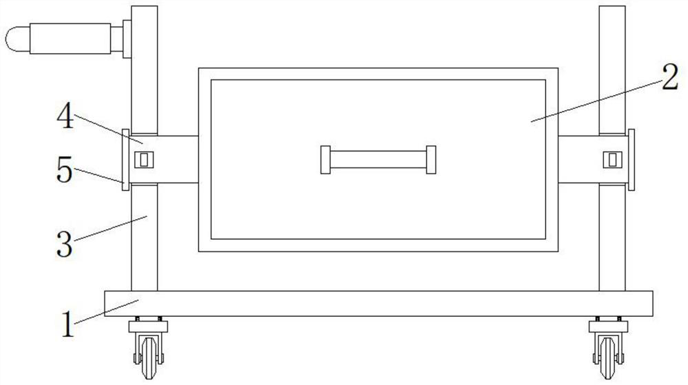
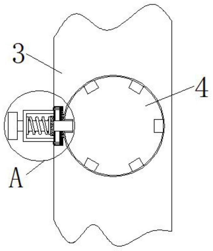
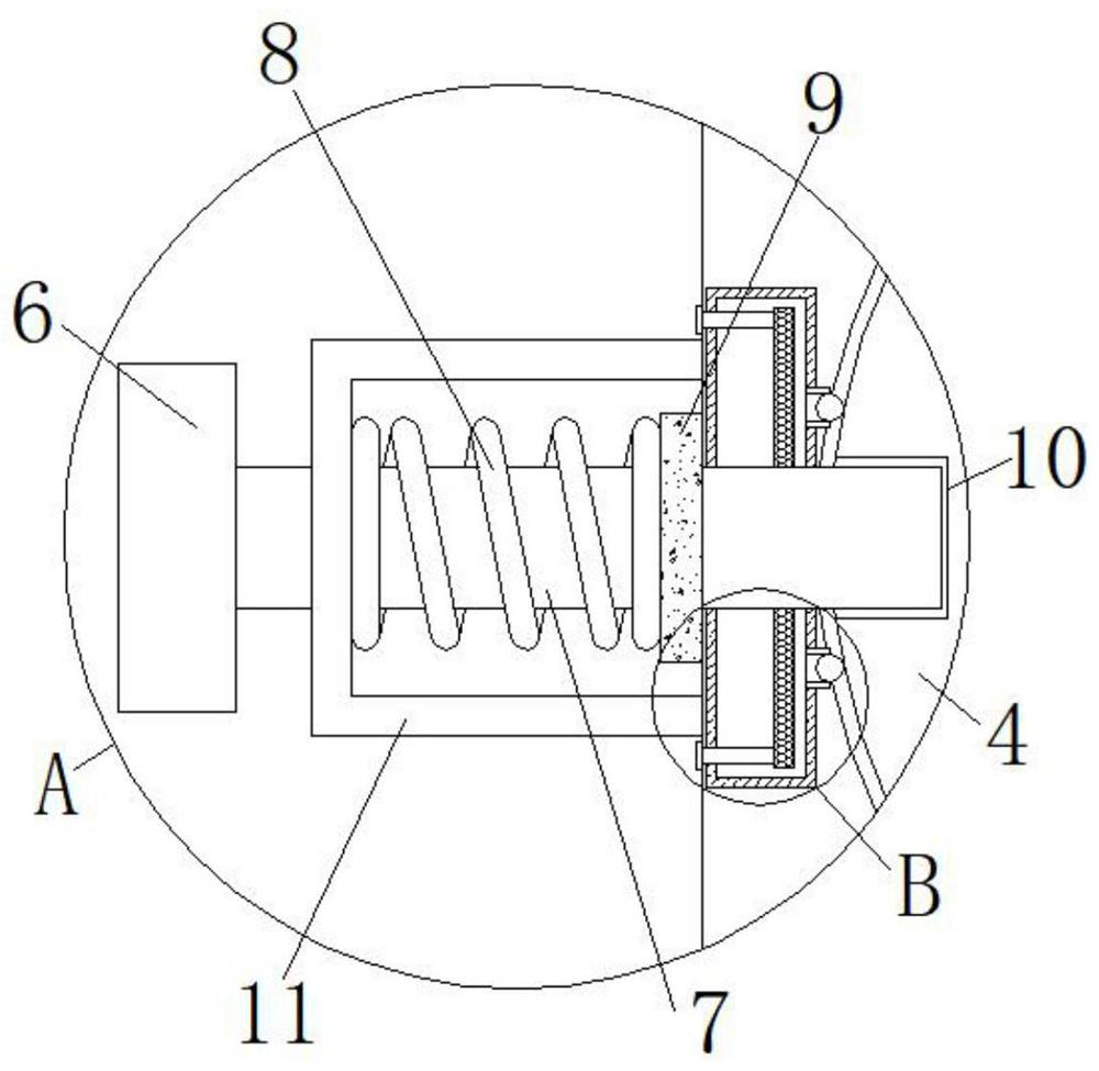
[0026] see Figure 1-5 , the present invention provides a technical solution: a gantry processing and its accessory head transfer device, including a base plate 1, the top surface of the base plate 1 is provided with two symmetrical support columns 3, and the two sides of the support column 3 are rotated and transmitted with fixed rotating shafts 4 , one side surface of the fixed rotating shaft 4 is fixed with a limit plate 5, the other side surface of the fix...


PUM


Abstract

The invention discloses a device for machining a gantry and transferring a right-angle milling head of the gantry. The device comprises a bottom plate, wherein pairwise symmetrical supporting columnsare arranged on the surface of the top end of the bottom plate, and fixing rotating shafts are rotationally transmitted to the surfaces of the two sides of the supporting columns; limiting plates arefixed to the surfaces of one sides of the fixing rotating shafts, and a storage box is fixed to the surfaces of the other sides of the fixing rotating shafts; and rubber base plates are fixed to the front surfaces of the supporting columns, U-shaped fixing frames are fixed to the front surfaces of the supporting columns, the rubber base plates are located on the inner sides of the U-shaped fixingframes, and fixing springs are arranged at the connecting positions between the U-shaped fixing frames and the rubber base plates. By arranging an inserting rod, a worker can conveniently and rapidlyadjust the angle of the storage box; by arranging sponge blocks, the surfaces of the fixing rotating shafts can be conveniently and rapidly lubricated, so that the rotating effect of the storage box is guaranteed; and by forming a fixing groove, the right-angle milling head can be conveniently and rapidly clamped and fixed, so that the stability of the device is improved.

Description

technical field [0001] The invention belongs to the technical field of transfer devices, and in particular relates to a transfer device for gantry processing and its accessory head. Background technique [0002] Attachment milling head, also known as right-angle milling head, attachment head, milling head, etc., belongs to machine tool accessories. It is mainly assembled on the gantry machining center and boring machine. It is used to expand the processing range of the machine tool. It can realize pentahedron processing and can be automatically grabbed by the machine tool ram. . It is a necessary accessory for gantry machine tools and boring machines, and has a good market prospect. In recent years, with the rapid development of my country's manufacturing industry, the demand for large machine tools has gradually increased, and domestic accessory head manufacturers have also increased year by year, so gantry processing and accessory head transfer devices are needed. [000...

Claims


Application Information

Patent Timeline
IPC IPC(8): B25H3/02B25H5/00
CPCB25H3/02B25H5/00
Inventor 朱文宝邢雨牛志强胡浩
Owner 上海山恩智能科技有限公司
Learn More