Cam bearing cap tapping device and application method thereof

A technology of cam bearings and bevel gears, which is applied in the field of cam bearing cap tapping devices, can solve the problems of low degree of automation, difficulty in controlling the depth, and inapplicable batch processing of products, etc., so as to improve work efficiency, facilitate post-cleaning, and have a reasonable structure Effect

Inactive Publication Date: 2020-10-30
艾斯迪工业技术股份有限公司
View PDF0 Cites 0 Cited by
  • Summary
  • Abstract
  • Description
  • Claims
  • Application Information

AI Technical Summary

Problems solved by technology

[0003] Most of the existing general-purpose tapping machines are folding-arm tapping machines, which are suitable for threaded hole processing of various parts, but have the following disadvantages: only one hole can be processed at a time, and the efficiency is low; the degree of automation is low, and manual control is required. Turning, the depth is not easy to control, and the combination of processes and operations cannot be carried out, which causes waste of personnel and is not suitable for batch processing of products; thread processing is entirely controlled by personnel, which is easy to cause missing processing, and after tapping, iron filings need to be cleaned specially, which is very trouble

Method used


Image

  • Cam bearing cap tapping device and application method thereof
  • Cam bearing cap tapping device and application method thereof
  • Cam bearing cap tapping device and application method thereof

Examples


Embodiment

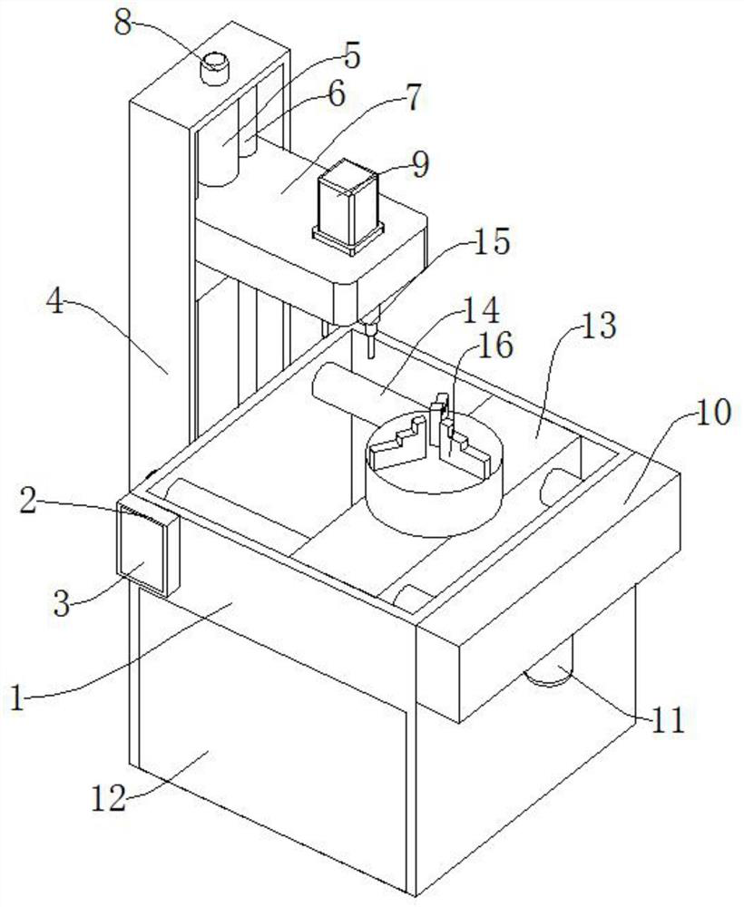
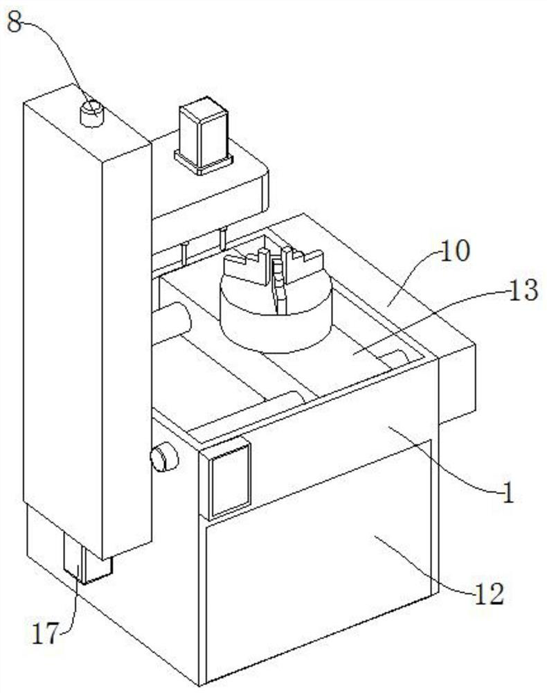
[0050] like Figure 1-Figure 7 As shown, a cam bearing cap tapping device includes a device housing 1, a lifting frame 7, a moving frame 13, and a recovery box 12. The front end of the device housing 1 is provided with a control box 2, and the control box 2 plays a protective role. The device housing The body 1 acts as a bearing, the control box 2 is provided with a control panel 3, the control panel 3 acts as a control, and the control box 2 is provided with a controller 24 inside;

[0051] The recovery box 12 is arranged on the inside of the device housing 1, and the recovery box 12 plays a collection role. The side of the device housing 1 is provided with a support column 4, and the support column 4 plays a supporting role. The lower end of the support column 4 is provided with a second servo motor 17. Two servo motors 17 play the role of energy supply, the inner side of the support column 4 is provided with a lifting screw 5, the front and rear sides of the lifting screw 5...


PUM


Abstract

The invention discloses a cam bearing cap tapping device and an application method thereof. The cam bearing cap tapping device comprises a device shell, a lifting frame, a moving frame and a recoverytank. The front end of the device shell is provided with a control box. A control panel is arranged on the control box. The control box is internally provided with a controller. The recovery tank is arranged inside the device shell. A supporting column is arranged on one side of the device shell. A second servo motor is arranged at the lower end of the supporting column. A lifting screw rod is arranged on the inner side of the supporting column. Sliding bars are arranged on the front and rear sides of the lifting screw rod correspondingly. The lifting frame is arranged on the lifting screw rod. The cam bearing cap tapping device has the beneficial effects that the cam bearing cap tapping device is reasonable in structure and implements reaming and tapping through one-time installation; anend cap is fixed to a three-jaw chuck and is protected against off-centering due to reciprocating disassembling and assembling; the cam bearing cap tapping device is easy to operate, automatic in operation and free of manual measurement and calculation, improves the working efficiency and facilitates cleaning; and scraps completely fall into the recovery tank to facilitate later-period cleaning.

Description

technical field [0001] The invention relates to the field of cam bearing cover tapping, in particular to a cam bearing cover tapping device and a use method thereof. Background technique [0002] The tapping machine has the advantages of lightness, flexibility, high efficiency, time-saving and labor-saving, not easy to rot teeth, and the tap is not easy to break. It avoids the limitations of lathes, drilling machines or manual tapping. It is suitable for mold machinery, plastic machinery, printing machinery, packaging machinery manufacturers , construction machinery, auto and motorcycle parts, aero-engines, rolling stock, tobacco machinery and other industries. [0003] Most of the existing general-purpose tapping machines are folding-arm tapping machines, which are suitable for threaded hole processing of various parts, but have the following disadvantages: only one hole can be processed at a time, and the efficiency is low; the degree of automation is low, and manual contr...

Claims


Application Information

Patent Timeline
Patent Type & Authority Applications(China)
IPC IPC(8): B23P23/02B23Q1/26
CPCB23P23/02B23Q1/26
Inventor 关俊秀
Owner 艾斯迪工业技术股份有限公司
Why Eureka
Try Eureka