River snail tail batch removing equipment for river snail processing

A field snail, batch technology, applied in the field of field snail tail batch removal equipment for field snail processing, can solve the problems of low work efficiency and labor, and achieve the effect of high work efficiency and convenient operation.

Inactive Publication Date: 2020-10-30
南京幸庄科技创新产业园管理有限公司
View PDF10 Cites 0 Cited by
  • Summary
  • Abstract
  • Description
  • Claims
  • Application Information

AI Technical Summary

Problems solved by technology

[0005] In order to overcome the shortcoming that the hand needs to constantly hold the pliers tightly after a long time, and people can only cut off one snail tail at a time, resulting in low work efficiency, the technical problem of the present invention is: to provide a kind of snail that is convenient for people to remove The removal of snail tails is relatively labor-saving, and it can cut off multiple snail tails at one time. It is a batch removal equipment for snail processing with high work efficiency.

Method used


Image

  • River snail tail batch removing equipment for river snail processing
  • River snail tail batch removing equipment for river snail processing
  • River snail tail batch removing equipment for river snail processing

Examples


Embodiment 1

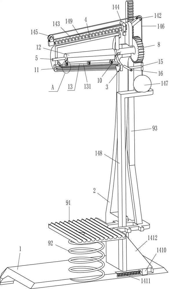
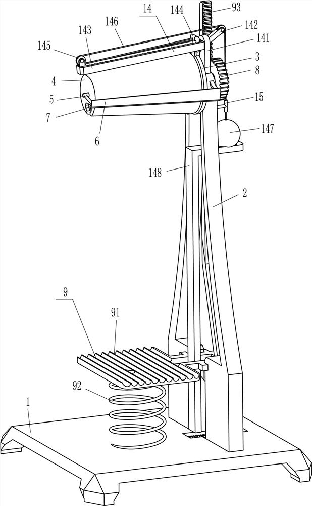
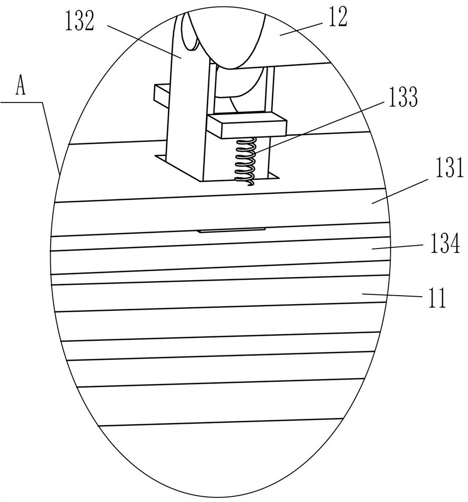
[0021] A kind of equipment for removing snail tails in batches for processing snails, such as Figure 1-Figure 3 As shown, it includes a base 1, a vertical plate 2, a notched annular plate 3, a conical cylinder 4, an L-shaped rod 5, a cutter 6, a gear 8, a driving mechanism 9, a rotating shaft 10, a limit rod 11, a camshaft 12 and A pressing mechanism 13, a riser 2 is fixedly connected in the middle of the top right side of the base 1, a driving mechanism 9 is provided between the riser 2 and the left side of the top of the base 1, and a rotating shaft 10 is connected in the middle of the upper part of the riser 2 in a rotating manner. The right end of 10 is fixedly connected with a gear 8 cooperating with the drive mechanism 9, the gear 8 is in contact with the drive mechanism 9, the left end of the rotating shaft 10 is fixedly connected with a conical cylinder 4, and the middle of the bottom of the conical cylinder 4 is horizontally provided with an opening 7 for placing snai...

Embodiment 2

[0028] On the basis of Example 1, such as figure 1 and figure 2 Shown, also comprise pusher mechanism 14, pusher mechanism 14 comprises support plate 141, the first guide pulley 142, return type plate 143, push plate 144, the second guide pulley 145, backguy 146, steel ball 147, L Type support bar 148, the 3rd spring 149, slide block 1410, the 4th spring 1411 and inclined block 1412, vertical plate 2 outer top middle is fixedly connected with support plate 141, and support plate 141 left side surface top is fixedly connected with back type plate 143 The push plate 144 is slidingly connected in the back-shaped plate 143, the lower part of the push plate 144 is in contact with the tapered tube 4, and the push plate 144 is also matched with the opening 7. The third spring 149 is connected between the left sides, the push plate 144 left side upper part is connected with a backguy 146, the second guide wheel 145 is installed on the left side of the return plate 143 top, and the f...

Embodiment 3

[0031] On the basis of embodiment 1 and embodiment 2, such as figure 1 and figure 2 As shown, it also includes a wire conduit 15 and a support frame 16, a support frame 16 is fixedly connected between the upper and lower sides of the vertical plate 2, a wire conduit 15 is fixedly connected to the right end of the support frame 16, and a pull wire 146 passes through the wire conduit 15 and its Cooperate.

[0032] When the steel ball 147 drives the push plate 144 to move to the left through the backguy 146, the wire guide 15 guides the backguy 146, and when the operator pulls the steel ball 147 to move up and reset, the backguy 146 is loosened, and the wire guide 15 also guides the backguy 146. guide. In this way, the pull wire 146 can be prevented from freely swinging and contacting the gear 8 to affect its rotation.


PUM


Abstract

The invention relates to removing equipment, in particular to river snail tail batch removing equipment for river snail processing. According to the river snail tail batch removing equipment for riversnail processing, people can conveniently cut off the tails of river snails, labor is saved, the tails of the river snails can be cut off at a time, and the working efficiency is high. The river snail tail batch removing equipment for field snail processing comprises a base, a vertical plate is fixedly connected to one side of the base, and a rotating shaft is rotatably connected to the side, away from the base, of the vertical plate in a penetrating mode. According to the invention, a proper amount of river snails are put into the opening; then a pedal is stepped to move downwards; a conicalbarrel rotates forwards to drive the river snails to rotate forwards through a limiting rod, a pressing plate presses the river snails, the river snails rotate forwards to make contact with a cutter,and the cutter cuts off the tails of the river snails, so that the tails of the river snails are cut off without holding signatures by people, labor is saved, operation is convenient, the tails of the river snails can be cut off at a time, and work efficiency is high.

Description

technical field [0001] The invention relates to a removal device, in particular to a batch removal device for snail tails for processing snails. Background technique [0002] The snail scientific name is Chinese round snail, and it is widely distributed in freshwater lakes, reservoirs, rice fields, ponds and ditches all over my country. Because of its tender and delicious meat, rich nutrition, and therapeutic effects such as clearing away heat, quenching thirst, and improving eyesight, it has become one of the favorite aquatic products, especially the southerners use it as a delicacy on the table. The tail of the snail is cut off to avoid the poisonous substances in the tail of the snail being eaten by people and affecting the health of the body. [0003] At present, most of the snail tails are cut off manually. First, people pick up a snail, clamp the snail tail with pliers, and then firmly hold the pliers to remove the snail tail. However, the snail shell is hard and requ...

Claims


Application Information

Patent Timeline
Patent Type & Authority Applications(China)
IPC IPC(8): A22C29/00
CPCA22C29/00
Inventor 李芳伟
Owner 南京幸庄科技创新产业园管理有限公司
Why Eureka
Try Eureka