Agricultural automatic corn seeding device
A technology of seeding device and corn, applied in agriculture, sowing, parts of seeding machine, etc., can solve the problems of unstable operation of seed metering device and inability to replenish corn seeds in time.
- Summary
- Abstract
- Description
- Claims
- Application Information
AI Technical Summary
Problems solved by technology
Method used
Image
Examples
Embodiment 1
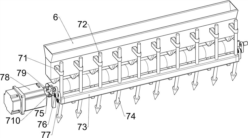
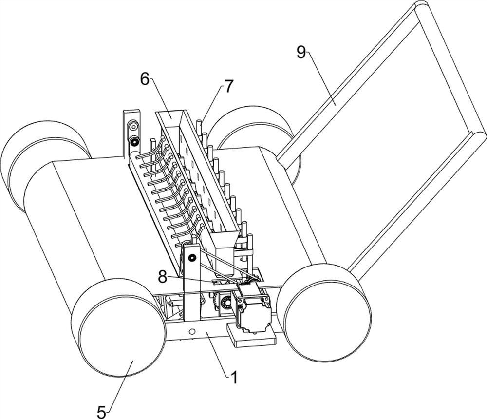
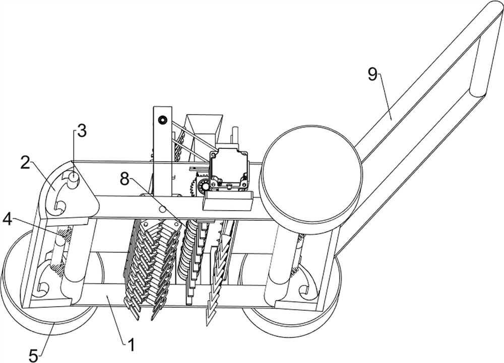
[0023] An automatic sowing device for agricultural corn, such as figure 1 , figure 2 , image 3 , Figure 4 with Figure 5 As shown, it includes a vehicle frame 1, a first connecting rod 3, an elastic member 4, a wheel 5, a hopper 6, a punching mechanism 7, a seeding mechanism 8 and a push rod 9, and arc grooves are arranged on four sides of the vehicle frame 1. 2. Between the arc grooves 2 on the left side and the arc grooves 2 on the right side, there is a first connecting rod 3 which slides and rotates, and the first connecting rods 3 are symmetrically connected with the frame 1 Elastic part 4, described elastic part 4 is tension spring, and first connecting rod 3 both ends are all fixedly connected with wheel 5, and vehicle frame 1 top is provided with loading hopper 6, and vehicle frame 1 is provided with punching mechanism 7, and vehicle The frame 1 is provided with a seeding mechanism 8, the loading hopper 6 is connected with the seeding mechanism 8, and the right ...
Embodiment 2
[0030] On the basis of Example 1, such as Image 6 As shown, it also includes a first bearing seat 10, a second rotating shaft 11, a belt conveyor 12, a first movable block 13, a second movable block 14, a lifting plate 15, a first connecting block 16, a second rotating rod 17, The second connection block 18, the third rotating rod 19, the earth-moving block 20 and the fixed rod 21, the front and rear symmetrically fixedly connected with the first bearing seat 10 on the vehicle frame 1, and the first bearing seat 10 tops are all provided with the first bearing seat 10 in a rotating manner. Two rotating shafts 11, a belt conveyor 12 is provided between the second rotating shaft 11 on the front side and the first rotating shaft 75, the second rotating shaft 11 is provided with the first movable block 13, and the first movable block 13 ends are arranged in a rotating manner. There is a second movable block 14, a lifting plate 15 is arranged between the ends of the second movable ...
PUM
 Abstract
Description
Claims
Application Information
 - R&D
- Intellectual Property
- Life Sciences
- Materials
- Tech Scout
- Unparalleled Data Quality
- Higher Quality Content
- 60% Fewer Hallucinations
Browse by: Latest US Patents, China's latest patents, Technical Efficacy Thesaurus, Application Domain, Technology Topic, Popular Technical Reports.
© 2025 PatSnap. All rights reserved.Legal|Privacy policy|Modern Slavery Act Transparency Statement|Sitemap|About US| Contact US: help@patsnap.com


