Combustion chamber double chamber bottom
A technology of combustion chamber and fuel oil, which is applied in the field of combustion chamber and can solve the problems of polluting fuel consumption and increasing the weight of combustion chamber
- Summary
- Abstract
- Description
- Claims
- Application Information
AI Technical Summary
Problems solved by technology
Method used
Image
Examples
Embodiment Construction
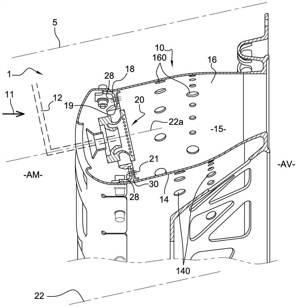
[0051] figure 1 The combustion chamber 10 of an aircraft gas turbine 1 according to the prior art is shown. With respect to the turbine (as indicated by arrow 11), upstream (AM) with respect to the general direction of airflow in the turbine 1, the turbine 1 has a compressor, not shown, in which the air is injected through the diffuser duct to the not shown. is compressed within the combustion chamber casing (phantom line 5) and then injected into the combustion chamber 10 mounted in this casing. Compressed air is fed into combustion chamber 10 and mixed with fuel before coming out of injector 12 . The gases from the combustion are directed to a high pressure turbine, not shown, located downstream (AV) of the combustion chamber 10 outlet. The annular combustion chamber 10 includes a radially inner annular wall 14 and a radially outer annular wall 16 whose upstream ends are connected by a substantially radially extending bottom wall 18 . The bottom wall 18 has a plurality of...
PUM
 Abstract
Description
Claims
Application Information
 - R&D Engineer
- R&D Manager
- IP Professional
- Industry Leading Data Capabilities
- Powerful AI technology
- Patent DNA Extraction
Browse by: Latest US Patents, China's latest patents, Technical Efficacy Thesaurus, Application Domain, Technology Topic, Popular Technical Reports.
© 2024 PatSnap. All rights reserved.Legal|Privacy policy|Modern Slavery Act Transparency Statement|Sitemap|About US| Contact US: help@patsnap.com


