Eureka AIR delivers breakthrough ideas for toughest innovation challenges, trusted by R&D personnel around the world.

In-sampling-tube static cone penetration testing device

A technology of static penetration testing and testing equipment, which is applied in the field of engineering survey and can solve problems such as depth mismatch, result deviation, and probe collision

Active Publication Date: 2020-10-27
GUANGZHOU MARINE GEOLOGICAL SURVEY
View PDF29 Cites 0 Cited by
  • Summary
  • Abstract
  • Description
  • Claims
  • Application Information

AI Technical Summary

Problems solved by technology

[0002] In engineering investigation, it is usually necessary to use a sampling tube to sample the soil, so as to facilitate the detection of the sample and avoid secondary disturbance. The sampling tube usually penetrates into the soil so that the soil is pressed into the inner cavity of the sampling tube. It is tightly fixed in the sampling tube, and the sample will be taken out during the test. In order to test the strength of the sample, etc., it is often tested by a static penetration probe before the sample is taken out. The current test method is to directly insert the probe manually. However, when the probe is inserted, it cannot guarantee its vertical advancement, which often makes the probe collide with the inner wall of the sampling tube, resulting in inaccurate test results, and the inclination of the probe when inserted is likely to cause the test results of the probe to differ from the sample. The depth does not correspond, resulting in deviation of the results, so we propose a static penetrating test device in the sampling pipe to solve the above problems

Method used


Image

  • In-sampling-tube static cone penetration testing device
  • In-sampling-tube static cone penetration testing device
  • In-sampling-tube static cone penetration testing device

Examples


Embodiment Construction

[0022] The following will clearly and completely describe the technical solutions in the embodiments of the present invention with reference to the accompanying drawings in the embodiments of the present invention. Obviously, the described embodiments are only some, not all, embodiments of the present invention. Based on the embodiments of the present invention, all other embodiments obtained by persons of ordinary skill in the art without making creative efforts belong to the protection scope of the present invention.

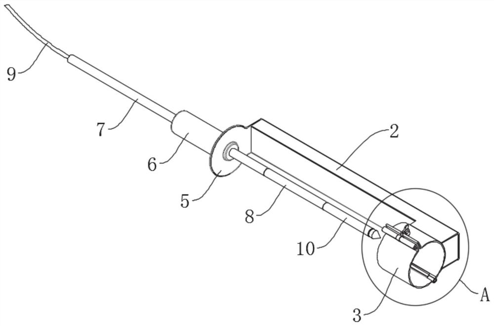
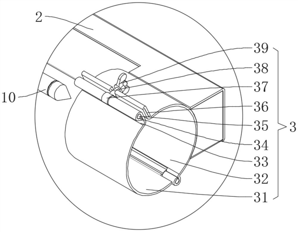
[0023] see Figure 1-3 , a static penetration test device in a sampling pipe, comprising a column 2, a fastener 3, a cover plate 5, a guide sleeve 6, a probe rod 7 and a probe 10, and one end (front end) of the column 2 is connected to the outside through the fastener 3 The sampling tube 1 is connected, preferably detachably connected, so that the sampling tube 1 can be detached from the fastener 3 of the column 2, the sampling tube 1 is used to store the samp...


PUM


Abstract

The invention discloses an in-sampling-tube static cone penetration testing device. The device comprises a stand column, a fastener, a cover plate, a guide sleeve, a feeler lever and a probe; the front end of the stand column is connected with an external sampling tube through the fastener; the cover plate is mounted at the rear end of the stand column; the outer side of the cover plate is connected with the guide sleeve for guiding; one end of the feeler lever extends forwards into the guide sleeve and is connected with the probe located on the inner side of the cover plate; the feeler leveris movably sleeved with the guide sleeve so that the feeler lever can move in the axial direction of the guide sleeve; a cable penetrates through the feeler lever from the other end of the feeler lever and then is connected with the probe so that data tested by the probe can be transmitted to the outside through the cable. The probe is linearly inserted into a sample, the probe is effectively prevented from making contact with the inner wall of the sampling tube; the moving depth of the probe corresponds to the depth of the sample, and therefore, test data of the sample of different depths canbe obtained conveniently. The device is suitable for static cone penetration tests in sampling tubes of different depths.

Description

technical field [0001] The invention relates to the technical field of engineering survey, in particular to a static penetrating test device in a sampling pipe. Background technique [0002] In engineering investigation, it is usually necessary to use a sampling tube to sample the soil, so as to facilitate the detection of the sample and avoid secondary disturbance. The sampling tube usually penetrates into the soil so that the soil is pressed into the inner cavity of the sampling tube. It is tightly fixed in the sampling tube, and the sample will be taken out during the test. In order to test the strength of the sample, etc., it is often tested by a static penetration probe before the sample is taken out. The current test method is to directly insert the probe manually. However, when the probe is inserted, it cannot guarantee its vertical advancement, which often makes the probe collide with the inner wall of the sampling tube, resulting in inaccurate test results, and the ...

Claims


Application Information

Patent Timeline
IPC IPC(8): G01N3/02G01N1/08
CPCG01N1/08G01N3/02G01N2203/04
Inventor 耿雪樵李柯良李力罗贤虎田烈余王世栋杨楠任旭光林康廖天保莫建刘碧荣
Owner GUANGZHOU MARINE GEOLOGICAL SURVEY
Why Eureka
Eureka Blog
Learn More