
Working face mining method

A mining method and working face technology, which is applied in ground mining, earth square drilling, underground mining, etc., can solve problems such as frequent safety accidents, tight mining continuity, waste of resources, etc.

Active Publication Date: 2020-10-27
BEIJING ZHONGKUANG INNOVATION ALLIANCE ENERGY & ENVIRONMENTAL SCI RES INST
View PDF6 Cites 1 Cited by
  • Summary
  • Abstract
  • Description
  • Claims
  • Application Information

AI Technical Summary

Problems solved by technology

[0005] Aiming at the problems existing in the prior art that the roadway must be excavated in advance for coal mining in the mining area, resulting in a large amount of engineering work in the early stage, tight excavation continuity, frequent safety accidents during the excavation process, and waste of resources caused by leaving coal pillars, the present disclosure aims at Due to the above limitations, the following technical problems need to be solved: the first mining face must be excavated in advance

Method used


Image

  • Working face mining method
  • Working face mining method
  • Working face mining method

Examples


Embodiment 1

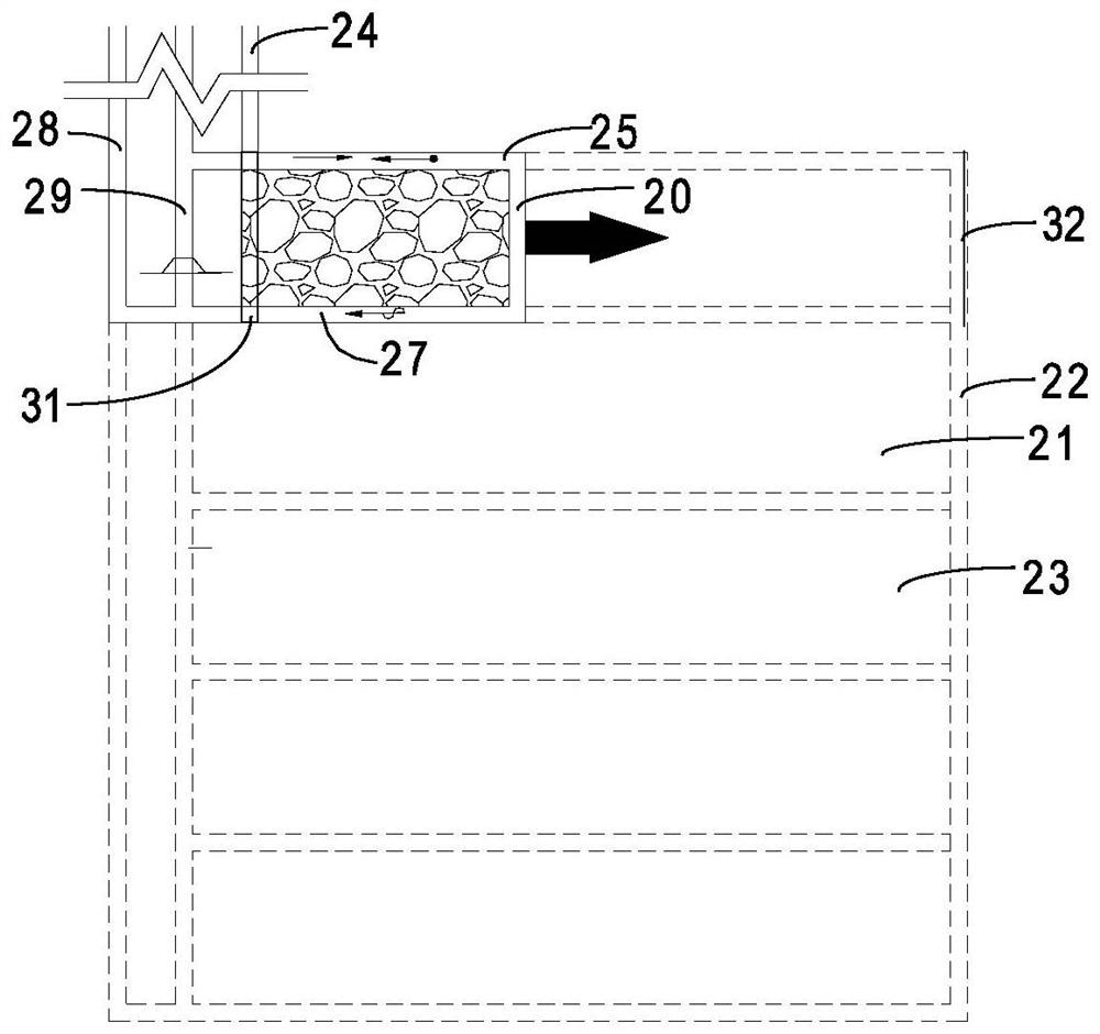
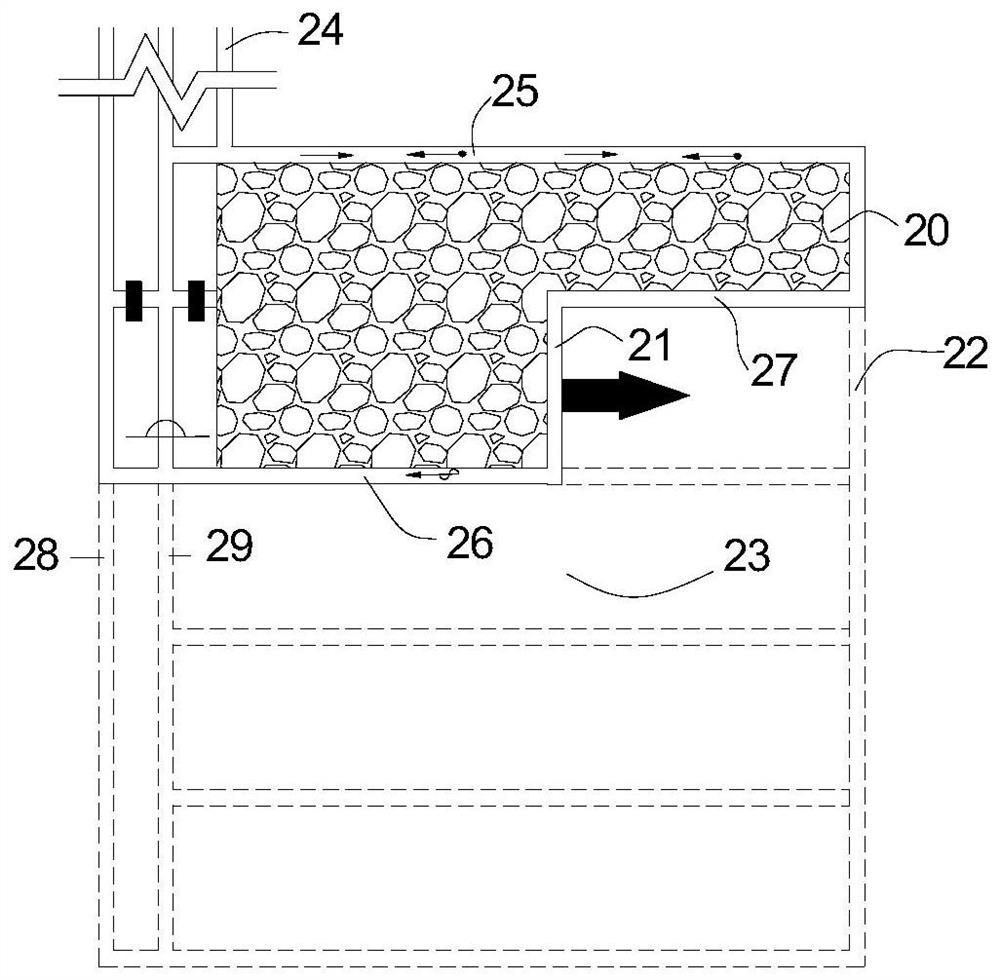
[0082] like figure 2 , image 3 As shown, in the mining method of double-side roadway retention in the embodiment of the present invention, the current mining area can include N working faces, and one side of the N working faces is directly provided with a return air roadway passage 29, a belt roadway passage 24 and a The passageway 28 of the track alley is connected to the wellhead to form a complete ventilation and transportation system. With the alternation of the working face, the three alleys extend to the new working face, and then connect with the new working face to form a complete transportation and return air system. The dotted line in the figure is the roadway formed in the subsequent sequence, and the solid line part is the roadway formed before or during the operation of the first mining face.

[0083] In this embodiment, the mining process of each working face includes:

[0084] Before mining, a cutout 31 is formed on the first mining face 20 to form the start...

Embodiment 2

[0095] like Image 6 , Figure 7 As shown, the difference between embodiment two of the present application and embodiment one is that the working face is arranged along the belt alley passage 24 and the track alley passage 28. The process of retaining alleys on both sides of the face, sealing the goaf, and moving the working face. This arrangement no longer needs to excavate the parallel channel in advance, but forms the parallel channel after coal mining, thus greatly reducing the huge workload caused by the advance excavation of the parallel channel, greatly shortening the well construction period, and no longer Coal pillars need to be reserved to save resources, and the effect achieved is consistent with the expected effect of the present disclosure.

[0096] like Figure 8 , Figure 9 As shown, the difference between the embodiment two of the present application and the embodiment one is that the working face is arranged along the belt road passage 24 and the track ro...


PUM

PropertyMeasurementUnit
Thicknessaaaaaaaaaa
Thicknessaaaaaaaaaa

Abstract

The invention relates to an underground mineral mining method and discloses a working face mining method. The mining process comprises the following steps of before mining, performing constructing onworking faces to form a cut hole so as to form a starting point of mining on the working faces; and performing gob-side entry retaining while mining at the two ends of each working face to respectively form a first gate way and a second gate way, wherein the first gate way and the second gate way form ventilation and transportation channels of the working faces. The mining method for bilateral entry retaining has the advantages and positive effects that compared with the prior art, the underground mineral mining method can ensure the ventilation of a whole coal mining area without the need ofperforming tunneling around the mining area to prepare a roadway; the gate ways do not need to be tunneled in advance when each working face in the mining area is mined, but the gate ways are formed after coal mining, thereby greatly reducing the huge workload caused by tunneling the gate ways in advance and greatly shortening the well construction period; and simultaneously, no coal pillars needto be reserved, thereby saving resources.

Description

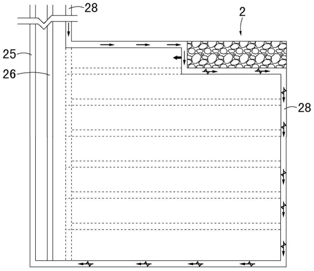
technical field [0001] The invention relates to a mining method of underground minerals, in particular to a mining method or mining method of underground coal mining. Background technique [0002] like figure 1 As shown, in the Chinese invention patent with the publication number CN105240013A, a longwall mining N00 method is disclosed, which includes at least one mining area 2, and a return air downhill passage 25 and a track downhill passage 26 are directly arranged on one side of the mining area 2. A belt downhill passage 28 is provided in communication with the other side from the wellhead in the production area. The return air downhill passage 25, the track downhill passage 26 and the belt downhill passage 28 are all connected to the wellhead, and the belt downhill passage 28 surrounds the entire mining area 2 and then connects with the return air downhill passage 25, forming the overall ventilation system of the mining area 2. [0003] Using the above mining mode, bef...

Claims


Application Information

Patent Timeline
IPC IPC(8): E21C41/18
CPCE21C41/18
Inventor 何满潮杨军王亚军高庆侯世林杨刚高玉兵
Owner BEIJING ZHONGKUANG INNOVATION ALLIANCE ENERGY & ENVIRONMENTAL SCI RES INST
Learn More