Drill rod assembly and drilling machine with same

A technology of drill pipe components and drill pipes, which is applied in the direction of drill pipes, drilling equipment and methods, drill bits, etc., and can solve the problems of large number of uses, high construction costs, and low construction efficiency

Pending Publication Date: 2020-10-27
江西基业良工桩机制造有限公司
View PDF2 Cites 0 Cited by
  • Summary
  • Abstract
  • Description
  • Claims
  • Application Information

AI Technical Summary

Problems solved by technology

[0004] Chinese patent document CN107938660A discloses a large-diameter bored pile casing construction method, and discloses how to drill holes and bury the casing. The specific diameter of the drill bit is greater than the outer diameter of the casing device, so that the hole wall can be greatly reduced. The frictional resistance of the soil to the casing is conducive to the lowering of the casing; however, as can be seen from the attached drawings, the drilling and lowering of the casing using the drill bit are two different equipments, resulting in a large number of equipment used and construction The cost is high, moreover, using two different equipment, when performing different construction steps, the equipment needs to be moved and replaced, resulting in low construction efficiency

Method used


Image

  • Drill rod assembly and drilling machine with same
  • Drill rod assembly and drilling machine with same
  • Drill rod assembly and drilling machine with same

Examples


Embodiment 1

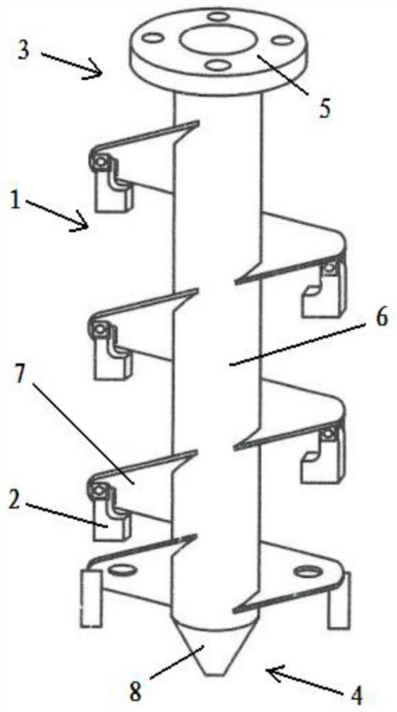
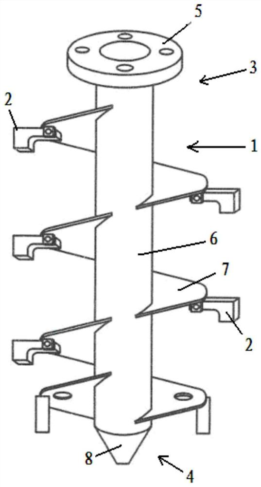
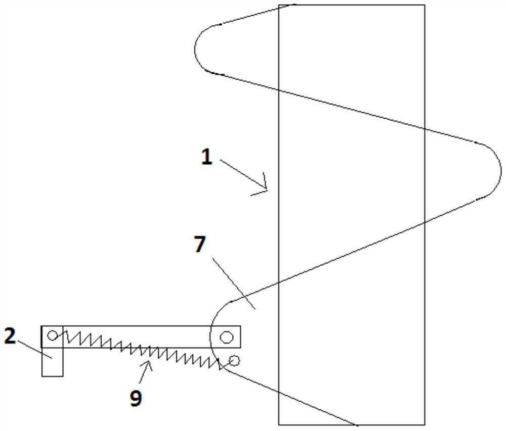
[0040] Such as figure 1 As shown, a drill pipe assembly includes: a drill pipe part 1; wherein, it also includes a cutting part 2, which can be flexibly connected to the drill pipe part 1 in a radially expandable manner, and is suitable for cooperating with the drill pipe part Boring is achieved, wherein the drill stem member has a drill diameter that is greater in the deployed state of the cutting member than in the undeployed state. Preferably, the drill pipe part has a power end 3, and a drilling end 4 opposite to the power end 3; as figure 2 As shown, the direction in which the cutting member 2 is radially deployed is from the drilling end 4 to the power end 3. Optionally, the cutting part 2 is hinged on the drill rod part 1 . The power end 3 of the drill rod assembly may also be provided with a connection structure for connecting with an external device, such as a flange structure 5. As a further improvement method, such as figure 1 As shown, the drill pipe component...

Embodiment 2

[0045] Such as Figure 4 As shown, this embodiment provides a drilling machine, including: a frame 11; wherein, also includes: a casing assembly 12, installed on the frame 11, including a casing 13 for protecting the hole wall; and the above The drill rod assembly 14 introduced in Embodiment 1, the drill rod assembly 14 is installed on the frame 11, at least partly movably embedded in the casing 13; the drill rod power part 28 is connected with the drill rod part , to provide power for the rotation of the drill rod component, preferably, the drill rod power component can be connected to the power end of the drill rod component, more preferably, can be detachably connected to the power end; the drilling rig It also includes a driving mechanism 15, which is installed on the frame 11 and connected with the casing assembly 12 and the drill pipe assembly 14 respectively, so as to realize the up and down movement of the casing assembly 12 and the drill pipe assembly 14 respectively....


PUM


Abstract

The invention provides a drill rod assembly. The drill rod assembly comprises a drill rod part, and further comprises a cutting part, the cutting part is movably connected to the drill rod part in a radial expansion mode and is suitable for matching with the drill rod part to achieve drilling, and the drilling diameter of the drill rod part in the expansion state of the cutting part is larger thanthat of the drill rod part in the non-expansion state of the cutting part. By means of the design, the drill diameter of the drill rod part can be smaller than or equal to the inner diameter of a pile casing part used for protecting a hole wall in a recycling state, so that the drill rod part can be movably embedded in a pile casing, a wall protection function can be achieved when the pile casingcan move up and down along with the drill rod assembly when the drill rod assembly drills holes, and when the cutting part is operated to be in an unfolded state, the drilling diameter of the drill rod is larger than the inner diameter of the pile casing, so that the hole diameter of a hole drilled by the drill rod assembly is at least larger than the inner diameter of the pile casing, and the frictional resistance of a soil body to the pile casing during descending is reduced.

Description

technical field [0001] The present invention relates to a drilling device and equipment for a construction site, in particular to a drill rod assembly and a drilling machine with the drill rod assembly. Background technique [0002] The construction of existing long spiral grouting piles is all to be drilled to the pile end bearing layer of design requirements earlier, then stop drilling and pour concrete, and then remove the drilling rig after the concrete pours to the floor surface, and insert the reinforcement cage. During on-site construction, there is often a certain distance between the elevation of the pile top and the floor surface (that is, a hole must be formed), and the conventional construction method is to only pour the concrete to the floor surface, so that the steel cage can be smoothly and cleanly installed. Otherwise, the position will be incorrect, or the drill pipe blade soil will fall into the hole, or the hole wall soil will be brought into and inserted ...

Claims


Application Information

Patent Timeline
Patent Type & Authority Applications(China)
IPC IPC(8): E21B17/22E21B10/44E21B7/02E21B15/00E21B19/02E21B17/00
CPCE21B17/22E21B10/44E21B7/02E21B15/00E21B19/02E21B17/00
Inventor 刘献刚梁毅江守慈张昆薜小波龙军
Owner 江西基业良工桩机制造有限公司
Why Eureka
Try Eureka