
Automobile maintenance tool

A technology for automobile maintenance and tools, which is applied in the direction of lifting devices, lifting frames, and parts of pumping devices for elastic fluids, etc. It can solve the problems of no better lifting effect and cannot be widely used, and achieves simple structure and convenient use , Ease of use

Inactive Publication Date: 2020-10-27
陈冬阳
View PDF0 Cites 1 Cited by
  • Summary
  • Abstract
  • Description
  • Claims
  • Application Information

AI Technical Summary

Problems solved by technology

[0004] The purpose of the present invention is to solve the shortcomings of the existing minority that have no better lifting effect when performing tilt maintenance and cannot be widely used for different car body shapes, and propose a kind of car maintenance tool

Method used


Image

  • Automobile maintenance tool
  • Automobile maintenance tool
  • Automobile maintenance tool

Examples


Embodiment 1

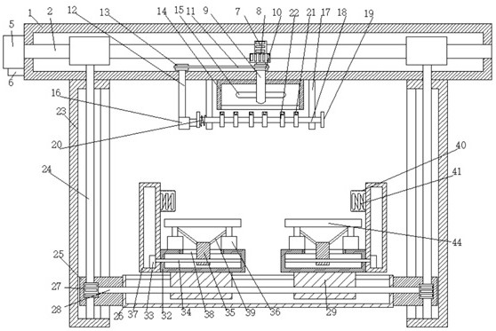
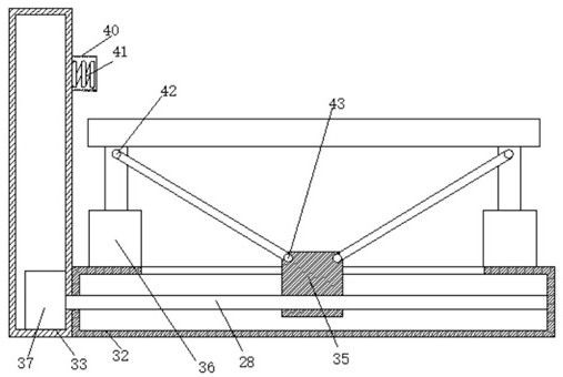
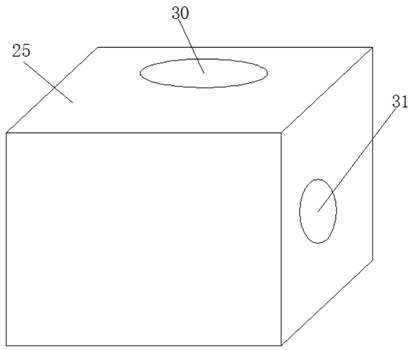
[0028] refer to Figure 1-5 , a kind of automobile maintenance tool, comprises top base 1, and the bottom of top base 1 is fixedly connected with two supporting columns 23, and one side of two supporting columns 23 is provided with second elongated hole, and the two supporting columns 23 rotate respectively Two second screw rods 24 are connected, and one end of the two second screw rods 24 is provided with a connecting block 25, and the tops of the two connecting blocks 25 are provided with a first threaded hole 30, and one side of the two connecting blocks 25 is A second threaded hole 31 is provided, and two first threaded holes 30 are threadedly connected with two second screw rods 24 respectively, and one end of the two connection blocks 25 is fixedly connected with the same base 26, and the base 26 is rotationally connected with a third Screw rod 28, the two ends of the 3rd screw rod 28 are all fixedly sleeved with the 3rd gear 27, and two 3rd gears 27 are respectively pos...

Embodiment 2

[0039] refer to Figure 1-5 , a kind of automobile maintenance tool, comprises top seat 1, and the bottom of top seat 1 is welded and connected with two supporting columns 23, and one side of two supporting columns 23 is all provided with the second long hole, and the two supporting columns 23 rotate respectively Two second screw rods 24 are connected, and one end of the two second screw rods 24 is provided with a connecting block 25, and the tops of the two connecting blocks 25 are provided with a first threaded hole 30, and one side of the two connecting blocks 25 is A second threaded hole 31 is provided, and two first threaded holes 30 are threadedly connected with two second screw rods 24 respectively, and one end of the two connecting blocks 25 is welded with the same base 26, and the base 26 is rotationally connected with a third Screw rod 28, the two ends of the third screw rod 28 are all welded with the third gear 27, and the two third gears 27 are respectively located...


PUM


Abstract

The invention belongs to the technical field of automobile maintenance, and particularly relates to an automobile maintenance tool. The automobile maintenance tool aims to solve the problems that a small number of existing tools do not have a better lifting effect during inclined maintenance and cannot be widely used for different vehicle shapes. According to the scheme, the automobile maintenancetool comprises a top base, wherein two supporting columns are fixedly connected to the bottom of the top base; second long holes are formed in one sides of the two supporting columns; two second screw rods are rotationally connected in the two supporting columns correspondingly; one of the ends of the two second screw rods is sleeved with a connecting block; first threaded holes are formed in thetops of the two connecting blocks; second threaded holes are formed in one of the ends of the two connecting blocks; the two first threaded holes are in threaded connection with the two second screwrods correspondingly; and one of the ends of the two connecting blocks is fixedly connected with the same base. The automobile maintenance tool is simple in structure, limiting suitable for differentvehicle types is achieved while lifting is carried out, and people can use the automobile maintenance tool conveniently.

Description

technical field [0001] The invention relates to the technical field of tools for automobile maintenance, in particular to an automobile maintenance tool. Background technique [0002] With the development of Chinese society and the increase in the number of cars, car maintenance is very common. When the car is being repaired, the bottom of the car needs to be repaired. However, the current lifting platform can only lift the car vertically, and cannot tilt the car. Inconvenient for local maintenance. [0003] It is now proposed that there is no better lifting effect when the existing minority is being tilted and maintained, and it cannot be widely used for different car body shapes. Contents of the invention [0004] The purpose of the present invention is to solve the shortcomings of the existing minority that have no better lifting effect and cannot be widely used for different car body shapes, and propose a kind of car maintenance tool. [0005] In order to achieve the...

Claims


Application Information

Patent Timeline
IPC IPC(8): B66F7/06B66F7/22B66F7/00B66F7/28F04D25/08F04D29/40
CPCB66F7/025B66F7/0608B66F7/0641B66F7/22B66F7/28F04D25/08F04D29/403
Inventor 陈冬阳
Owner 陈冬阳
Learn More