Eureka AIR delivers breakthrough ideas for toughest innovation challenges, trusted by R&D personnel around the world.

Special rigid track for crane

A crane and rail technology, which is applied to the field of special rigid rails for cranes, can solve the problem of inconvenient alignment connection of rail ends, and achieve the effects of quick alignment connection, enhanced anchoring effect, and firm fixed installation.

Pending Publication Date: 2020-10-27
HEFEI KIWI HEAVY MACHINERY CO LTD
View PDF0 Cites 0 Cited by
  • Summary
  • Abstract
  • Description
  • Claims
  • Application Information

AI Technical Summary

Problems solved by technology

[0004] The purpose of the present invention is to provide a special rigid track for cranes, which is used to solve the problem that it is not convenient to align and connect the ends of the track when installing the track

Method used


Image

  • Special rigid track for crane
  • Special rigid track for crane
  • Special rigid track for crane

Examples


Embodiment Construction

[0018] The following will clearly and completely describe the technical solutions in the embodiments of the present invention with reference to the accompanying drawings in the embodiments of the present invention. Obviously, the described embodiments are only some, not all, embodiments of the present invention. Based on the embodiments of the present invention, all other embodiments obtained by persons of ordinary skill in the art without making creative efforts belong to the protection scope of the present invention.

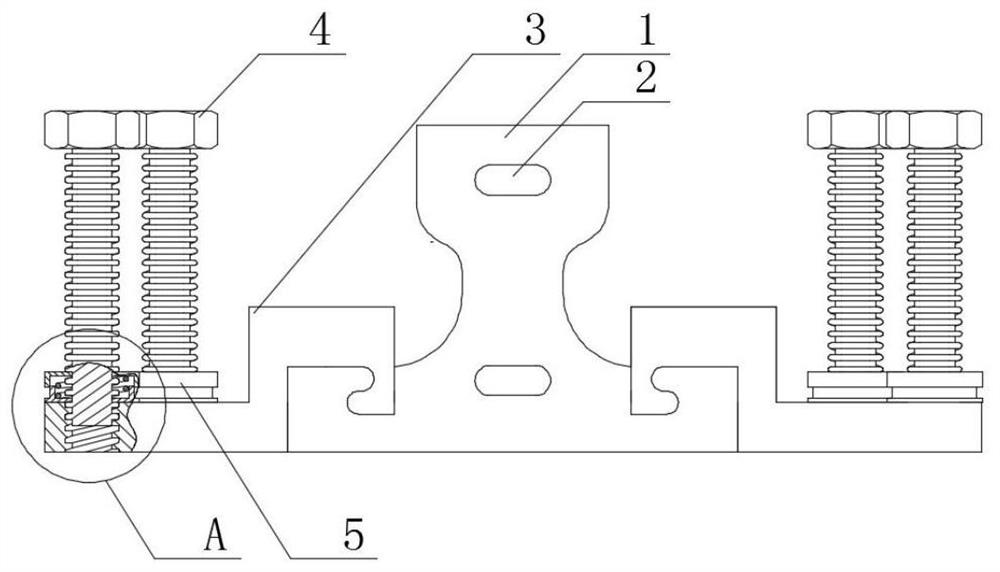
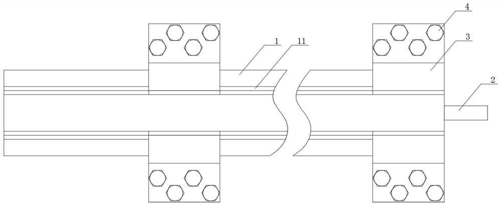
[0019] see Figure 1-4 , the present invention provides a technical solution, a special rigid track for cranes, including a track monomer 1, the two ends of the track monomer 1 are respectively provided with slots close to the center line, and the slots on one side of the track monomer 1 The insertion rod 2 is plugged in, and the upper surface of the front and back flanges of the bottom end of the track monomer 1 is respectively provided with chute 11 along th...


PUM


Abstract

The invention relates to the technical field of crane tracks, in particular to a special rigid track for a crane. The special rigid track for the crane comprises a track monomer, wherein inserting grooves are formed in the positions, close to a center line respectively, of the two end surfaces of the track monomer, inserting rods are inserted into the inserting groove in the end surface of one side of the track monomer, sliding grooves are formed in the upper surfaces of flanges on the front surface and the back surface of the bottom end of the track monomer in the axial direction, a pluralityof fixing parts are slidably clamped to the track monomer through the sliding grooves, the lower surfaces of the extending ends of the fixing parts are flush with the lower surface of the track monomer, fixing bolts are connected to the upper surfaces of the extending ends of the fixing parts through threaded through holes in a sleeving mode, elastic bodies are connected to the peripheries, closeto f the upper surfaces of the extending ends of the track monomer, of the fixing bolts in a sleeving mode, each elastic body comprises a bottom shell body, an upper shell body and a spring, the bottom shell bodies and the upper shell bodies are of mutually-sleeved cavity structures, the springs are located inside the cavity structures, and the springs are connected to the peripheries of the fixing bolts in a sleeving mode. The problem that when a track is installed, the ends of the track are inconvenient to align and connect is solved.

Description

technical field [0001] The invention relates to the technical field of crane rails, in particular to a special rigid rail for cranes. Background technique [0002] A crane refers to a multi-action hoisting machine that lifts vertically and carries heavy objects horizontally within a certain range. In the workshop, bridge cranes are generally used to lift and transfer heavy objects. Among them, the bridge crane is a kind of hoisting machine that is horizontally mounted on the rails at both ends of the factory building, the lifting trolley can run along the main girder, the main girder can run longitudinally along the two rails, and use the space below to lift and transport materials. The two ends of the main girder of the bridge crane are respectively fixed on the end girder, and the end girder runs along the rails on both sides of the factory building through rollers. Among the components of the crane, the crane rail plays a very important role in carrying the crane for sa...

Claims


Application Information

Patent Timeline
IPC IPC(8): B66C7/08
CPCB66C7/08
Inventor 杨孝先
Owner HEFEI KIWI HEAVY MACHINERY CO LTD
Why Eureka
Eureka Blog
Learn More