Electric booster for vehicle

A booster and electric technology, which is applied in the direction of brakes, vehicle components, transmissions, etc., can solve the problems of increased size, unfavorable noise, and unfavorable layout of electric boosters

Active Publication Date: 2020-10-27
HYUNDAI MOBIS CO LTD
View PDF7 Cites 0 Cited by
  • Summary
  • Abstract
  • Description
  • Claims
  • Application Information

AI Technical Summary

Problems solved by technology

Therefore, the size of the electric booster increases, which is disadvantageous in terms of layout when setting up other parts of the vehicle
In addition, the hollow space defined around the guide pin serves as a ringing space for the noise generated by the operation of the gear, which is disadvantageous in terms of noise

Method used


Image

  • Electric booster for vehicle
  • Electric booster for vehicle
  • Electric booster for vehicle

Examples


Embodiment Construction

[0041] Hereinafter, an electric booster for a vehicle will be described below through various examples of embodiments with reference to the accompanying drawings. It should be noted that the drawings are not drawn to precise scale and may be exaggerated in thickness of lines or size of components for convenience and clarity of description only. Also, the terms as used herein are defined by considering the functions of the present invention, and may be changed according to user's or operator's habit or intention. Therefore, definitions of terms should be made according to the overall disclosure set forth herein.

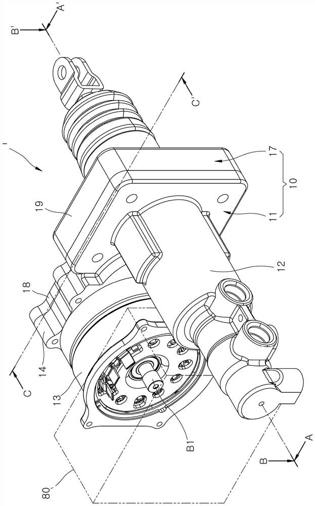
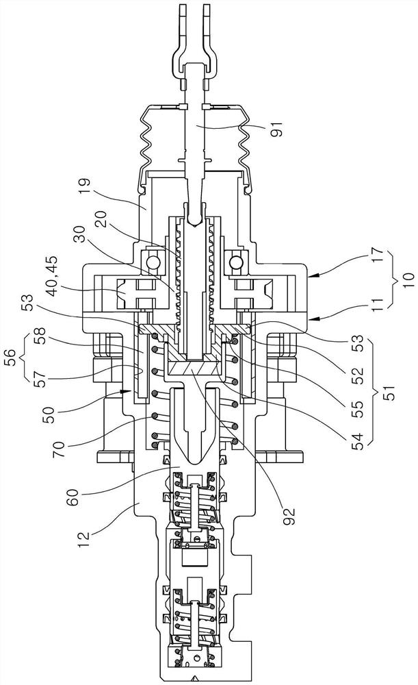
[0042] figure 1 is a perspective view schematically showing an illustration of an example of an electric booster for a vehicle according to an embodiment of the present disclosure, and figure 2 is along figure 1 A cross-sectional view taken on line A-A'.

[0043] refer to figure 1 and figure 2 , an electric booster 1 for a vehicle according to an embodiment of...


PUM


Abstract

An electric booster for a vehicle includes a housing having a cylinder structure capable of supporting a hydraulic pressure formed therein; a screw bolt installed in the housing; a screw nut screwed to the screw bolt; a gear unit configured to transfer a rotational force of a motor to the screw nut; a rotation preventing unit coupled with the screw bolt, and configured to prevent rotation of the screw bolt by being brought into contact with the housing; and a piston moved by being pressed by the screw bolt, and configured to form a hydraulic pressure in the housing.

Description

technical field [0001] Exemplary embodiments of the present disclosure relate to an electric booster for a vehicle, and more particularly, to an electric booster for a vehicle for improving braking performance using electric power. Background technique [0002] Typically, a vehicle's brakes create friction by pushing on brake pads to slow down a moving vehicle or keep it at a stop. In this regard, since the driver's strength is limited, the braking performance is improved by boosting the force by the booster. Although a booster using a vacuum has been employed in the prior art, an electric booster using a motor has recently been adopted. Electric boosters require a structure that can support forces acting in the axial direction and radial direction when the brake is operated, and a structure that can convert the rotation of the motor into the screw when the torque of the motor is transmitted to the screw through gears. Rotation prevention structure that prevents the screw ...

Claims


Application Information

Patent Timeline
Patent Type & Authority Applications(China)
IPC IPC(8): B60T13/74
CPCB60T13/745B60T13/74B60T8/3265F16H2025/204F16H2025/2081F16D65/18F16D2121/20F16H25/24
Inventor 尹承现
Owner HYUNDAI MOBIS CO LTD
Why Eureka
Try Eureka