
Optical fiber quality analysis method and device, electronic equipment and storage medium

A quality analysis and optical fiber technology, applied in the direction of testing optical fiber/optical waveguide equipment, measuring devices, nuclear methods, etc., can solve the problems of inability to analyze the development trend of optical cable quality, the probability of cable failure, low efficiency, and low accuracy

Pending Publication Date: 2020-10-23
GUANGXUN SCI & TECH WUHAN
View PDF18 Cites 3 Cited by
  • Summary
  • Abstract
  • Description
  • Claims
  • Application Information

AI Technical Summary

Problems solved by technology

[0004] In recent years, some manufacturers have developed supporting OTDR management software, which can replace part of the manual analysis through the fixed algorithm of the software, but usually the software can only analyze the curves collected by the OTDR equipment produced by the manufacturer itself, and cannot be used in the market.
[0005] It can be seen from the above that the current optical cable quality analysis method mainly relies on manual or single software formula analysis, which has low efficiency and low accuracy, and cannot analyze the development trend of optical cable quality and predict the future failure probability of optical cable

Method used


Image

  • Optical fiber quality analysis method and device, electronic equipment and storage medium
  • Optical fiber quality analysis method and device, electronic equipment and storage medium
  • Optical fiber quality analysis method and device, electronic equipment and storage medium

Examples


Embodiment Construction

[0052] In order to make the purpose, technical solution and advantages of the present invention clearer, the present invention will be described in further detail below in conjunction with the accompanying drawings, and the described embodiments should not be considered as limiting the present invention, and those of ordinary skill in the art do not make any All other embodiments obtained under the premise of creative labor belong to the protection scope of the present invention.

[0053]Those skilled in the art can understand that although the following description involves many technical details related to the embodiments of the present invention, this is only an example for illustrating the principle of the present invention, and does not imply any limitation. The present invention can be applied to occasions other than the technical details exemplified below, as long as they do not deviate from the principle and spirit of the present invention.

[0054] In addition, in ord...


PUM


Abstract

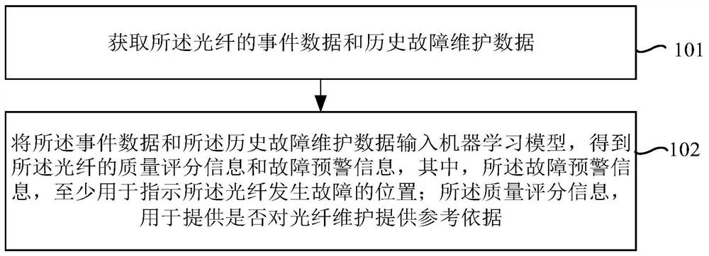
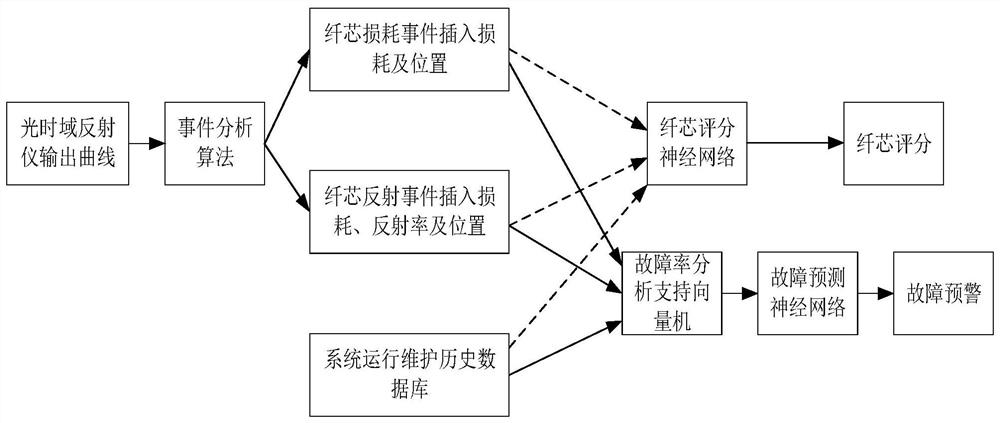
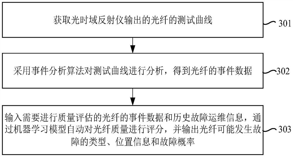
The invention provides an optical fiber quality analysis method and device, electronic equipment and a storage medium. The method comprises the following steps: acquiring event data and historical fault maintenance data of the optical fiber; inputting the event data and the historical fault maintenance data into a machine learning model to obtain quality scoring information and fault early warninginformation of the optical fiber, the fault early warning information being at least used for indicating a fault position of the optical fiber, and wherein the quality scoring information is used forproviding a reference basis for optical fiber maintenance or not.

Description

technical field [0001] The invention relates to the technical field of optical cable quality analysis, in particular to an optical fiber quality analysis method, device, electronic equipment and storage medium. Background technique [0002] OTDR (Optical Time Domain Reflectometer, Optical Time Domain Reflectometer) is an optical time domain reflectometer, which transmits optical pulses into the optical fiber, uses Rayleigh scattering and Fresnel reflection, and receives the returned curve information at the OTDR port to link status to monitor. When the light pulse is transmitted in the fiber, it will be scattered and reflected due to the nature of the fiber itself, connectors, splices, bending or other similar events. OTDR is widely used in the optical cable maintenance industry. Maintenance personnel analyze the quality of optical fiber by collecting OTDR test curves. [0003] The usual analysis method is to test the spare fiber through OTDR, collect the test curve, impor...

Claims


Application Information

Patent Timeline
IPC IPC(8): G06N3/04G06N3/08G06N20/10G01M11/00G01M11/02
CPCG06N3/08G06N20/10G01M11/02G01M11/30G06N3/045
Inventor 张小娇陈星云余磊周治柱
Owner GUANGXUN SCI & TECH WUHAN
Learn More