
Elastic rolling device

A rolling device and elastic technology, applied in the direction of packaging material feeding device, packaging, transportation packaging, etc., can solve the problems of breakage, insufficient interference extrusion force of packaging materials, wear of two pressing surfaces, etc.

Pending Publication Date: 2020-10-23
KUNMING DINGCHENGQIXIN TECH CO LTD
View PDF0 Cites 0 Cited by
  • Summary
  • Abstract
  • Description
  • Claims
  • Application Information

AI Technical Summary

Problems solved by technology

The existing splicing device consists of a pair of rolling dies respectively installed on the rotating rollers. Since the two rolling dies work in rigid rolling extrusion, it is inevitable that the two pressing surfaces will be worn or produced due to the existence of stress. The dents cause the rolling die to have insufficient interference extrusion force on the packaging material, which affects the pressing effect of the new and old strips. Therefore, the existing technology requires frequent replacement of the rolling die, which not only affects work efficiency, but also increases maintenance costs. At the same time, the impact and vibration force will be transmitted to the fastening screw, causing the stress concentration to cause the deformation and breakage of the fastening screw, and even cause the rolling die to fall out and cause a safety accident. For this reason, the machine has to be stopped for replacement, and frequent failures, replacement will take place Affect work efficiency and have potential safety hazards

Method used


Image

  • Elastic rolling device
  • Elastic rolling device
  • Elastic rolling device

Examples


Embodiment Construction

[0022] The present invention will be further described below in conjunction with the accompanying drawings.

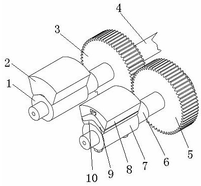
[0023] The elastic rolling device provided by the present invention includes two rollers 1, 7 which rotate relatively, and rolling dies respectively arranged on the two rollers 1, 7, wherein: the roller shaft 4 of the roller 1 and the power motor (not shown in the figure) given), the roller shaft 4 is provided with a driving gear 3, and the roller shaft 6 of the roller 7 is provided with a driven gear 5 meshing with the driving gear 3, which can be driven by the power motor through the driving, driven gear 3, 5 Make the two rollers 1, 7 rotate synchronously, and then drive the two rolling dies 2, 8 to rotate;

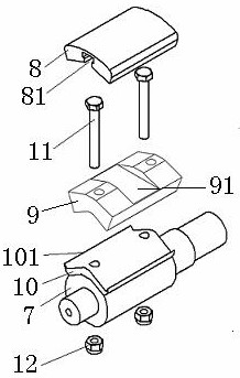
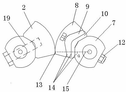
[0024] Elastic pad 9 and supporting pad 10 are arranged between the rolling mold 8 of the roller 7 in the two rollers 1,7 and the roller 7; the shape of the elastic pad 9 is adapted to the bottom shape of the rolling mold 8, and Both radial sides of the support...


PUM


Abstract

The invention provides an elastic rolling device. The elastic rolling device comprises two rollers which rotate relatively and rolling dies which are arranged on the two rollers respectively. The elastic rolling device is characterized in that an elastic cushion is arranged between the rolling dies and the rollers of at least one of the two rollers, and the shape of the elastic cushion is matchedwith the shape of the bottoms of the rolling dies. When the two rolling dies extrude relatively, stress concentration generated by rigid rolling extrusion can be fundamentally solved through the elastic cushion or the elastic cushion and a supporting cushion, abrasion or dents of the pressing faces of the two rolling dies are reduced, the service life of the device is prolonged, and the pressing effect of new and old strips is guaranteed; and through the inclined face arrangement of all the combination positions, the problem that fastening screws are deformed and broken due to stress concentration is solved, the situation that production is affected and even safety accidents happen due to the fact that connecting pieces are deformed and broken is avoided, the pressing effect of the new andold strips is guaranteed, and safety production is guaranteed.

Description

technical field [0001] The invention relates to an elastic rolling device, in particular to an elastic rolling device for splicing sheets and strips, and belongs to the technical field of printing and packaging equipment. Background technique [0002] In the printing and packaging machinery and equipment, when the packaging materials are processed in the form of strips and rolls, some packaging materials need to use glueless splicing devices to realize the connection of the new and old packaging strips. The glueless splicing device rotates the two pressing surfaces of the two rolling dies in opposite directions at the same speed, and presses the new and old strips entering the two pressing surfaces to complete the splicing. The existing splicing device consists of a pair of rolling dies respectively installed on the rotating rollers. Since the two rolling dies work in rigid rolling extrusion, it is inevitable that the two pressing surfaces will be worn or produced due to the...

Claims


Application Information

Patent Timeline
IPC IPC(8): B65H19/18B65B41/12
CPCB65B41/12B65H19/18B65H2701/1944
Inventor 杨正勇高贤杰何贤励邢俊美高空
Owner KUNMING DINGCHENGQIXIN TECH CO LTD
Learn More