


Quick Research
Generate reliable direction feasibility study reports for your R&D in just a few steps.

Technical Q&A
Discover and master advanced knowledge NOW. Basics, ideas, possibilities, all at once.

Find Solutions
As an expert in R&D theories, this can generate solutions to your technical problems instantly.

Evaluate Feasibility
Analyze your overall solution with one click, know your potential R&D risks in advance.

Monitor Landscape
Get weekly tech updates, stay abreast of the latest tech innovations and key insights.
Foldable variable-diameter cylinder horizontal transfer trolley
A transfer vehicle and cylinder technology, which is applied to trolleys, motor vehicles, multi-axle trolleys, etc., can solve the problem that it can only be applied to cylinders of the same diameter.
- Summary
- Abstract
- Description
- Claims
- Application Information
AI Technical Summary
Problems solved by technology
Method used
Image

Examples
Embodiment 1
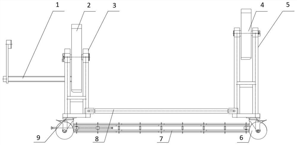
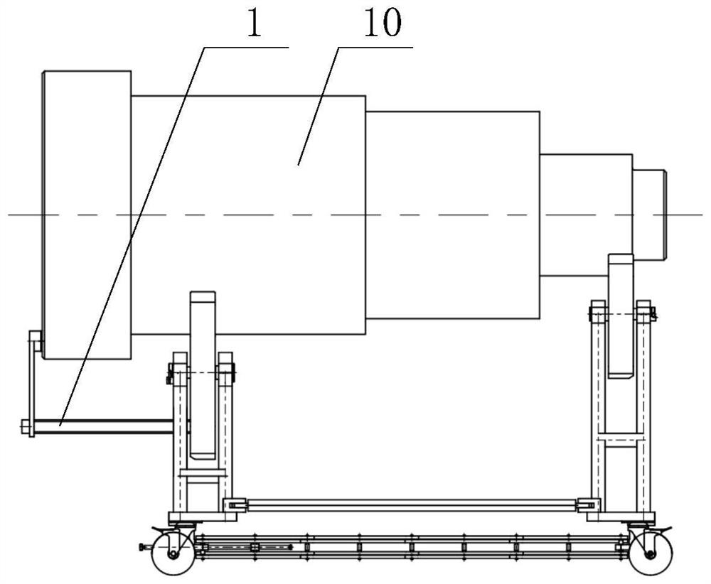
[0051] Such as Figure 1-Figure 8 As shown, the collapsible variable-diameter column horizontal transfer vehicle includes bracket I3 and bracket II5 arranged oppositely, the bottom of the bracket I3 and bracket II5 are connected by a connecting mechanism, and the bracket I3 and bracket II5 Wheels 6 are provided at the bottom of the bottom, and bracket I2 and bracket II4 are respectively rotated on the bracket I3 and bracket II5. Specifically, the bracket I3 is an A-shaped frame including two symmetrically arranged, 2 A rotating shaft is arranged between the two A-shaped frames, and a through hole is arranged on the bracket I2, and a bearing is arranged in the through hole, and the rotating shaft is installed in the bearing, and the bracket II5 has the same structure as the bracket I3 , the tops of the bracket I2 and the bracket II4 respectively protrude from the tops of the bracket I3 and the bracket II5, specifically, the heights of the bracket I2 and the bracket II4 are equa...
Embodiment 2
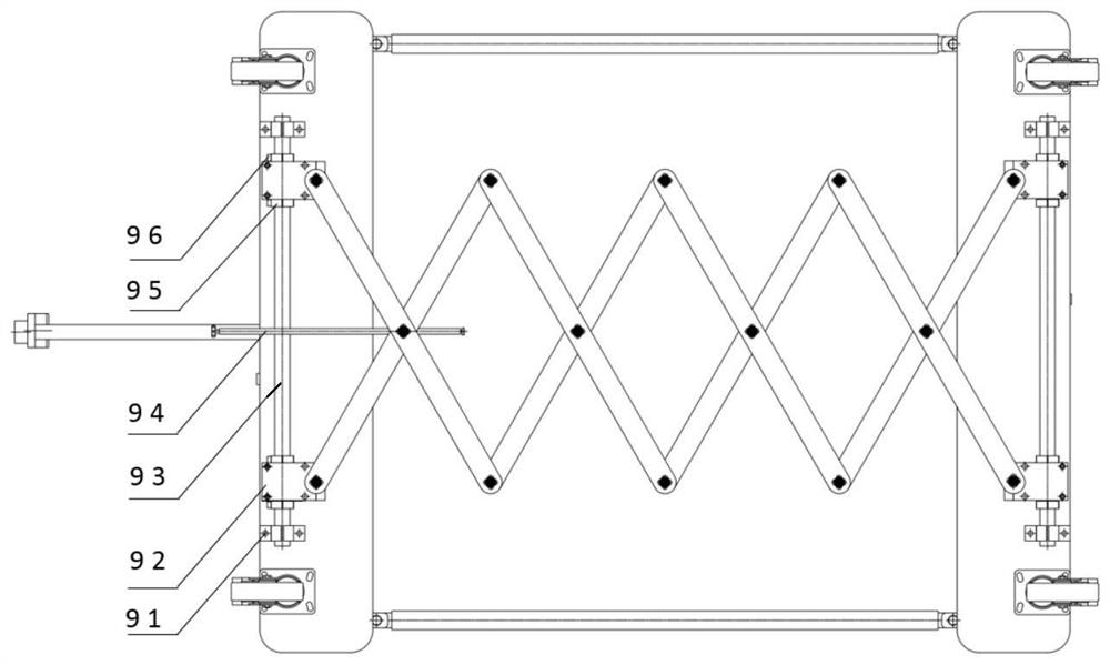
[0054] Such as Figure 1-Figure 8 As shown, this embodiment is based on Embodiment 1. The connecting mechanism includes a scissors structure 7 and a limit mechanism 9. The bottoms of the bracket I3 and the bracket II5 are all provided with a limit mechanism 9. The scissors structure 7 Arranged between two limit mechanisms 9, the limit mechanism 9 is used to fix the end of the scissor structure 7; the limit mechanism 9 includes two symmetrically arranged supports 91, and the two supports 91 A guide rail 93 is arranged between them, and two slide blocks 92 are slidably arranged in the guide rail 93, and the two slide blocks 92 are detachably connected with the two ends of the same end of the scissor structure 7 respectively, and the guide rail 93 slides Limiting blocks 95 are provided on both sides of the block 92 , the limiting blocks 95 can slide on the guide rail 93 , and the limiting blocks 95 are fixed on the guide rail 93 by locking screws 96 .
[0055] In this embodiment...
Embodiment 3
[0058] Such as Figure 1-Figure 8 As shown, this embodiment is based on Embodiment 2, and the scissors structure 7 is a double-layer scissors structure, and the two layers are connected by a connecting column, and a rotating rod 94 is arranged on the connecting column at the end; two bottom plates A connecting rod is provided through screws; a support rod 8 is detachably provided between the bracket I3 and the bracket II5; the support rod 8 is a telescopic rod.
PUM
 Abstract
Description
Claims
Application Information
 - R&D Engineer
- R&D Manager
- IP Professional
- Industry Leading Data Capabilities
- Powerful AI technology
- Patent DNA Extraction
Browse by: Latest US Patents, China's latest patents, Technical Efficacy Thesaurus, Application Domain, Technology Topic, Popular Technical Reports.
© 2024 PatSnap. All rights reserved.Legal|Privacy policy|Modern Slavery Act Transparency Statement|Sitemap|About US| Contact US: help@patsnap.com