Electric push type charging pile and push method

A push-type, charging pile technology, used in electric vehicle charging technology, charging stations, electric vehicles, etc.

Active Publication Date: 2020-10-23
温州电尾猴科技有限公司
View PDF7 Cites 2 Cited by
  • Summary
  • Abstract
  • Description
  • Claims
  • Application Information

AI Technical Summary

Problems solved by technology

However, the prior art uses a dodge door to clo

Method used


Image

  • Electric push type charging pile and push method
  • Electric push type charging pile and push method
  • Electric push type charging pile and push method

Examples


Embodiment 1

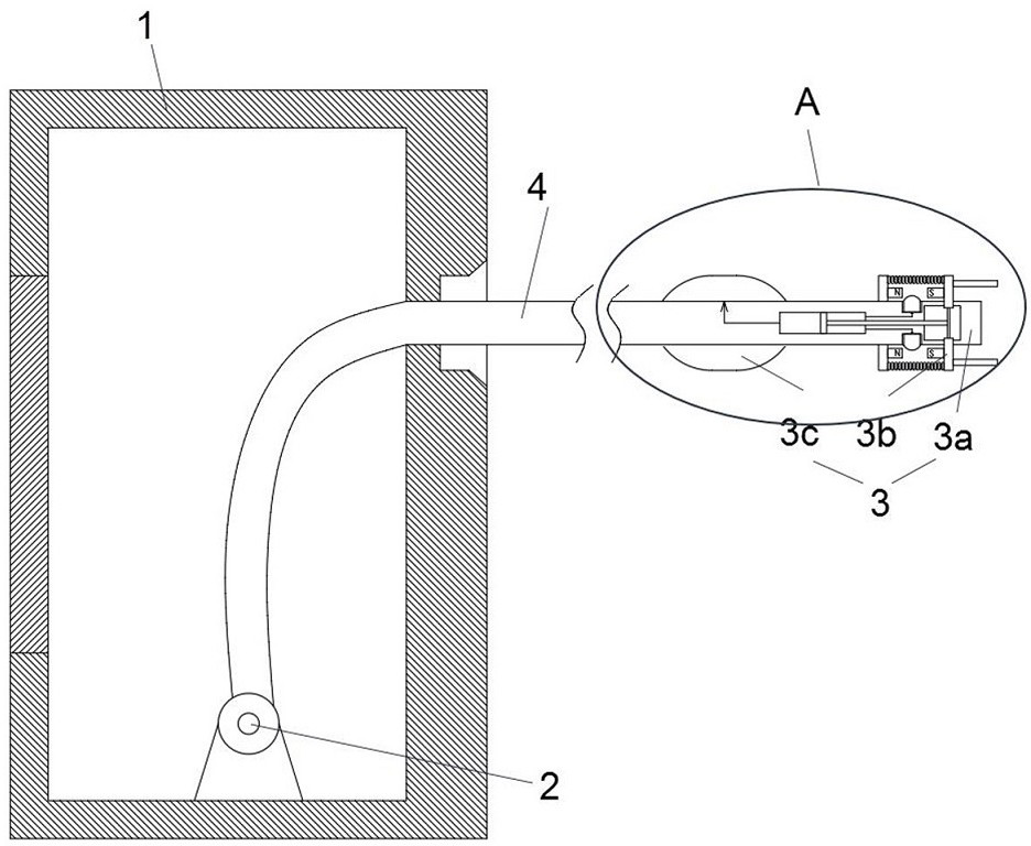
[0016] Such as Figure 1 to Figure 4 As shown, the present application provides an electric push-type charging pile, which at least includes a pile body 1 , a winding assembly 2 , a charging assembly 3 and a charging cable 4 . The winding assembly 2 is rotatably arranged in the pile body 1 . One end of the charging cable 4 is connected to the winding assembly 2 . The other end of the charging cable 4 is connected to the charging assembly 3 . The charging assembly 3 is used to connect with the vehicle, and then realize the charging of the vehicle. When the winding assembly 2 rotates, the charging cable 4 can be wound on the winding assembly 2 , and then the charging cable 4 can be retracted. The pile body 1 can be provided with a storage battery or it can be directly connected to 220V civilian electricity, and then the electrical energy required for charging can be transmitted to the charging assembly 3 through the electrical connection between the charging cable 4 and the p...

Embodiment 2

[0023] The electric push-type charging pile of this embodiment can be used to charge electric vehicles such as new energy vehicles. When the charging card is brought close to the card swiping device, the two will generate induction to complete identity authentication and identification. At this time, the charging plug 3a can be in a power-on state (for example, a controller can be provided in the pile body 1. When it detects the card swiping operation, Then the charging plug 3a will be connected to the 220V civilian power system). Subsequently, the driver can hold and drag the charging plug 3a, so that the charging cable 4 is detached from the winding assembly 2, and at this time, the charging plug 3a can be inserted into the charging hole of the vehicle.

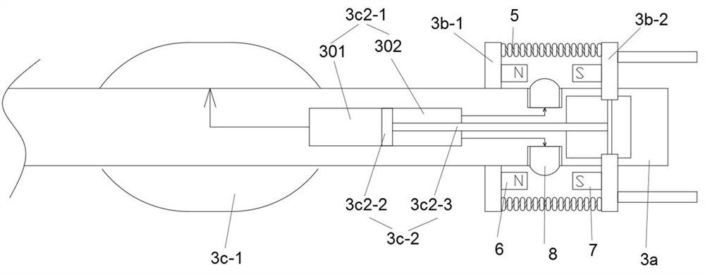
[0024] When the charging plug 3a is inserted into the charging hole, the right side of the second fixing plate 3b-2 first contacts the bottom of the charging hole, and then when the charging plug continues to be inserted in...


PUM


Abstract

The invention discloses an electric push type charging pile and a push method. The electric push type charging pile at least comprises a pile body, a winding assembly, a charging assembly and a charging cable. The charging assembly at least comprises a charging plug, a pushing part and a clamping part. The pushing part and the clamping part are arranged on the charging plug in a mutual coupling mode, in the process that the charging plug is inserted into a charging hole of a vehicle, the charging hole can apply counter-acting force to the pushing part so that the pushing part can work, and after the pushing part works, needed driving force can be provided for the clamping process of the clamping part and the charging hole. The pushing method at least comprises the following steps that a pushing part and a clamping part which are coupled with each other are arranged on the charging plug; and according to configuration of the pushing part, in the process that the charging plug is inserted into the charging hole, the charging hole can apply counter-acting force to the pushing part, so that the pushing part can provide required driving force for the clamping process of the clamping part and the charging hole. According to the invention, no extra triggering part is needed, and the charging plug can be popped up in time.

Description

technical field [0001] The invention belongs to the technical field of automobile charging equipment, and in particular relates to an electric push-type charging pile and a push method. Background technique [0002] New energy vehicles refer to all other energy vehicles except gasoline and diesel engines, including fuel cell vehicles, hybrid vehicles, hydrogen energy vehicles and solar vehicles. Its exhaust gas emission is relatively low. The function of the charging pile is similar to that of a fuel dispenser in a gas station. It can be fixed on the ground or wall and installed in public buildings (public buildings, shopping malls, public parking lots, etc.) and residential parking lots or charging stations. , can charge various models of electric vehicles according to different voltage levels. The input end of the charging pile is directly connected to the AC grid, and the output end is equipped with a charging plug for charging the electric vehicle. The prior art, such ...

Claims


Application Information

Patent Timeline
IPC IPC(8): B60L53/16B60L53/31B60L53/60
CPCB60L53/16B60L53/31B60L53/60Y02T10/70Y02T10/7072Y02T90/12Y02T90/14
Inventor 朱亮徐术学朱明轩朱明朗
Owner 温州电尾猴科技有限公司
Why Eureka
Try Eureka