Screening mechanism with adjustable screening hole size
A technology of sieve size and sieving, applied in sieve, filtration separation, solid separation, etc., can solve problems such as low sieving efficiency
- Summary
- Abstract
- Description
- Claims
- Application Information
AI Technical Summary
Problems solved by technology
Method used
Image
Examples
specific Embodiment approach 1
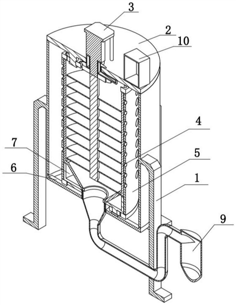
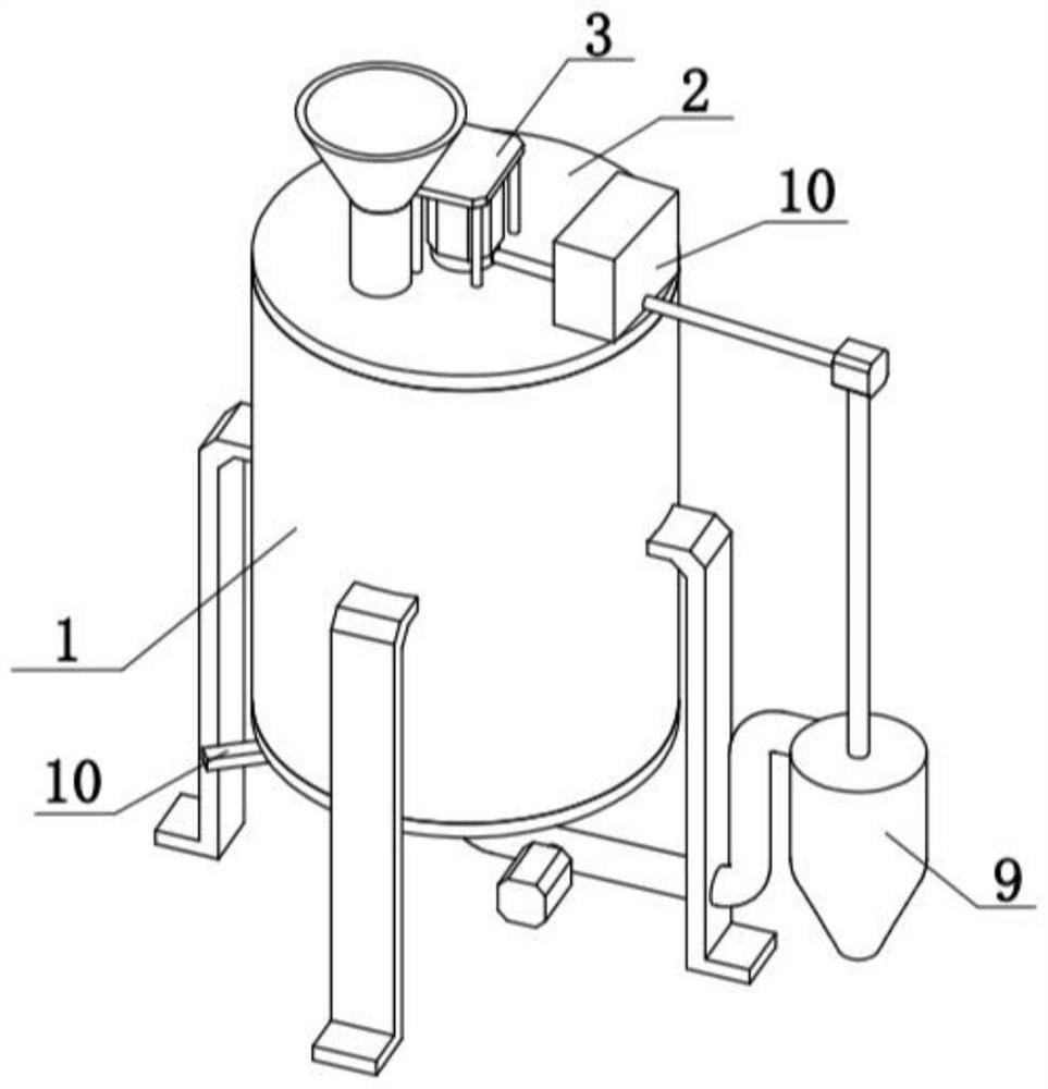
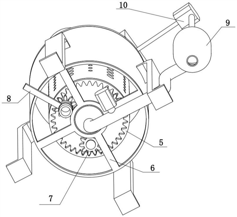
[0034] Combine below Figure 1-12 Describe this embodiment, the screening mechanism with adjustable sieve hole size includes a support frame 1, a differential assembly 2 and an auxiliary frame 6, the differential assembly 2 is fixedly connected to the support frame 1, and the auxiliary frame 6 is fixedly connected to the support frame 1 The lower end of the sieving mechanism with adjustable sieve hole size also includes a drive centrifugal assembly 3, an inner sieve bucket 4, an outer sieve bucket 5, an adjustment assembly 7, a push assembly 8, a solid-liquid separation assembly 9 and a sprinkler assembly 10. The centrifugal assembly 3 is fixedly connected to the differential assembly 2, the inner sieve bucket 4 is fixedly connected to the adjustment assembly 7, the adjustment assembly 7 is rotatably connected to the auxiliary frame 6, the outer sieve bucket 5 is rotatably connected to the adjustment assembly 7, and the push assembly 8 Fixedly connected to the adjustment assem...
specific Embodiment approach 2
[0037] Combine below Figure 1-12 To illustrate this embodiment, the differential assembly 2 includes an upper cover 2-1, a feed pipe 2-2, a differential shaft 2-3 and a differential wheel 2-4, and the upper cover 2-1 is fixedly connected to the support frame 1 The upper end of the feed pipe 2-2 is fixedly connected to the upper cover 2-1, and the lower part of the upper cover 2-1 is evenly distributed with a plurality of differential shafts 2-3, and the plurality of differential shafts 2-3 are rotationally connected There are differential wheels 2-4.
[0038] Feeding is carried out through the feed pipe 2-2, and the diameter of the feed pipe 2-2 controls the feeding speed of the sieved material, which can make the present invention in the best sieving state and prevent the material from being screened too quickly or In the case of material accumulation, multiple differential wheels 2-4 can reduce the high-speed rotation driven by the centrifugal assembly 3 to the low-speed rot...
specific Embodiment approach 3
[0040] Combine below Figure 1-12 To illustrate this embodiment, the drive centrifugal assembly 3 includes a drive frame 3-1, a drive motor 3-2, a drive gear 3-3, a rotating shaft 3-4 and a spiral plate 3-5, and the drive frame 3-1 is fixedly connected to On the upper cover 2-1, the drive motor 3-2 is fixedly connected to the drive frame 3-1, the drive gear 3-3 is fixedly connected to the output shaft of the drive motor 3-2, and the rotating shaft 3-4 is fixedly connected to the drive motor On the output shaft of 3-2, the spiral plate 3-5 is fixedly connected on the rotating shaft 3-4, and the spiral plate 3-5 is rotatably connected in the inner sieve bucket 4.
[0041] The driving motor 3-2 drives the driving gear 3-3 to rotate, and the driving gear 3-3 meshes to drive a plurality of differential wheels 2-4 to rotate, and the plurality of differential wheels 2-4 play a high rotational speed output by the driving motor 3-2 Reduce the speed to the lower rotation speed of the o...
PUM
 Abstract
Description
Claims
Application Information
 - R&D Engineer
- R&D Manager
- IP Professional
- Industry Leading Data Capabilities
- Powerful AI technology
- Patent DNA Extraction
Browse by: Latest US Patents, China's latest patents, Technical Efficacy Thesaurus, Application Domain, Technology Topic, Popular Technical Reports.
© 2024 PatSnap. All rights reserved.Legal|Privacy policy|Modern Slavery Act Transparency Statement|Sitemap|About US| Contact US: help@patsnap.com


