
Ball type self-ligating bracket

A self-locking bracket and ball-type technology, applied in the direction of brackets, arch wires, etc., can solve the problems of complex structure and easy to fall off, and achieve the effect of easy opening and locking operation, meeting clinical needs, and stable locking

Pending Publication Date: 2020-10-23
ZHEJIANG PROTECT MEDICAL EQUIP
View PDF0 Cites 1 Cited by
  • Summary
  • Abstract
  • Description
  • Claims
  • Application Information

AI Technical Summary

Problems solved by technology

However, at present, many self-locking structures have complex structures, and are prone to fall off after long-term use.

Method used


Image

  • Ball type self-ligating bracket
  • Ball type self-ligating bracket
  • Ball type self-ligating bracket

Examples


Embodiment 1

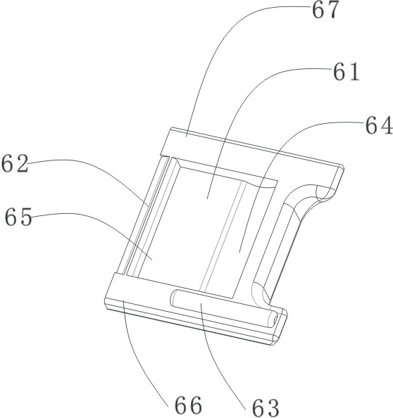
[0030] Such as figure 1 As shown, a ball-type self-locking bracket includes a base plate 1 and a bracket main body 2 arranged on the base plate 1. The bracket main body 2 has an archwire groove 3, and left and right sides of the archwire groove 3 have left and right sides. Working wing 5 and right working wing 4. Such as figure 2 As shown, there is a chute 45 on the right working wing 4, the chute 45 is used to accommodate the sliding locking piece 6, and a ball groove 43 is also provided on the bottom surface of the chute 45. Such as Figure 5 As shown, a ball structure is arranged in the ball groove 43 . Such as Figure 6 As shown, the ball 7 includes a ball bushing 72 and a ball shaft 71. The ball 7 is elastic. The ball 7 may be elastic as a whole, or the ball bushing 72 may be elastic. The ball 7 is formed by assembling the ball shaft sleeve 72 and the ball shaft 71 , and the ball shaft sleeve 72 can rotate through the ball shaft 71 . The ball 7 is partly located in...

Embodiment 2

[0034] Example 2 as Figure 9 As shown, other structures of this embodiment are the same as Embodiment 1, except that the ball structure in this embodiment is as follows Figure 10 The structure shown, specifically includes Figure 12 ball shaft shown and as Figure 11 Ball bushing shown. The roller main shaft in this embodiment is a square rod, and the ball bushing is fixed on the square rod, unlike in Embodiment 1, which can rotate around the ball shaft. However, the ball shaft and the ball bushing are elastic as a whole, so they are still applicable. Correspondingly, the shape of the ball groove 43 for accommodating the balls has also been adaptively changed. For details, see Figure 9 shown.


PUM


Abstract

A ball type self-ligating bracket comprises a bracket body with an arch wire groove, a left working wing and a right working wing, a sliding locking plate is further arranged on the bracket body, a sliding groove for containing the sliding locking plate is formed in one of the working wings of the bracket body, a ball groove is formed in the bottom face of the sliding groove, and a ball structureis arranged in the ball groove. The ball structure is partially located in the ball groove and partially protrudes out of the bottom face of the sliding groove. A ball locking groove matched with theball structure of the protruding part is formed in the lower surface of the corresponding sliding lock plate; and the ball structure has elasticity. According to the ball type self-ligating bracket, due to the fact that the elastic ball structure is arranged, and the locking positioning groove and the unlocking positioning groove are formed in the positions corresponding to the sliding locking plate, locking of the locking plate is more stable. Meanwhile, the unlocking and locking operation is more convenient.

Description

technical field [0001] The invention relates to a bracket for orthodontics, in particular to a self-locking bracket for orthodontics. Background technique [0002] Brackets are the most commonly used components in orthodontic treatment. At present, there are various self-locking brackets in clinical application, which greatly facilitates the locking of the arch wire in the bracket by clinicians. However, at present, many self-locking structures have complex structures, and are prone to fall off after long-term use. Contents of the invention [0003] Aiming at the problems existing in the background technology, the present invention provides a ball type self-locking bracket with simple structure and convenient locking. [0004] The technical scheme of the present invention is as follows: a ball-type self-locking bracket, including a bracket main body with an archwire groove and left and right working wings, a sliding locking piece is also arranged on the bracket main body...

Claims


Application Information

Patent Timeline
Patent Type & Authority Applications(China)
IPC IPC(8): A61C7/28
CPCA61C7/287
Inventor 董小娟胡毅王建均杨捷吴超方继庆
Owner ZHEJIANG PROTECT MEDICAL EQUIP
Learn More