Self-propelled automatic quantitative fertilization device

A quantitative fertilization, self-propelled technology, applied in fertilization devices, planting methods, fertilizer distributors, etc., can solve the problems of poor fertilization uniformity, low work efficiency, and the inability of fertilizers to adjust the amount of fertilization.

Pending Publication Date: 2020-10-23
ZHAOTONG CO LTD YUNNAN TOBACCO CO LTD
View PDF0 Cites 0 Cited by
  • Summary
  • Abstract
  • Description
  • Claims
  • Application Information

AI Technical Summary

Problems solved by technology

[0002] At present, a shovel or an iron pick is usually used to dig a soil pit at the root of the crops, and then bury the fertilizer in the soil pit for fertilization. Not only is the labor intensity high and the efficiency is low, the depth of the pit and the amount of fertilizer applied It is also difficult to control, and it is easy to damage the root system of the crops during the digging process, and the fertilization site is not accurate; The operation is difficult, bending over for a long time and manual work is a great test for the hands, waist and body of the operator, the work efficiency is low, and the uniformity of fertilization is poor
[0003] Although the existing fertilization device overcomes the defects of high difficulty, low efficiency and uneven fertilization amount of the manual fertilization method to a certain extent, the injection rod and the injection pipe are inserted into the soil together by manpower during fertilization, and then the injection pipe is inserted into the soil. Only when the fertilizer is pulled out can the fertilizer be injected into the soil, so the work intensity is high, and it cannot work smoothly when the soil is compacted or there are stones in the soil. work efficiency; in addition, the fertilizer applicator cannot adjust the amount of fertilizer according to the actual needs of the crops, and the structure is complex

Method used


Image

  • Self-propelled automatic quantitative fertilization device
  • Self-propelled automatic quantitative fertilization device
  • Self-propelled automatic quantitative fertilization device

Examples


Embodiment Construction

[0015] The present invention will be further described below in conjunction with the accompanying drawings, but the present invention is not limited in any way. Any transformation or replacement based on the teaching of the present invention belongs to the protection scope of the present invention.

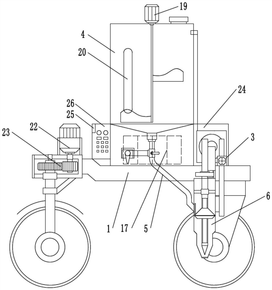
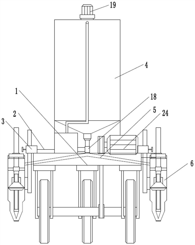
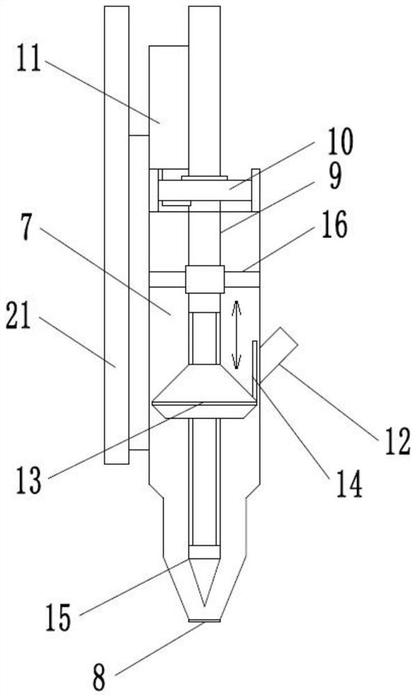
[0016] as attached Figure 1~4 The shown self-propelled automatic quantitative fertilization device comprises a walking vehicle frame 1, and a fertilizer applicator 6 and a material container 4 arranged on the walking vehicle frame 1, and the material container 4 is connected to the fertilizer applicator 6 through a feed pipe 5, and the walking Both sides of the rear part of the vehicle frame 1 are provided with horizontal supports 2 respectively, and fertilization adjustment seats 3 dynamically matched with them are arranged on each horizontal support 2, and the fertilization device 6 is arranged on the fertilization adjustment seats 3; wherein, the fertilization The device 6 inc...


PUM


Abstract

The invention discloses a self-propelled automatic quantitative fertilization device which can effectively reduce operation difficulty and labor intensity and improve fertilization efficiency. The self-propelled automatic quantitative fertilization device comprises a walking frame, wherein horizontal supports are arranged on two sides of the walking frame respectively, a fertilization adjusting seat is arranged on each horizontal support, and a fertilizer applicator is arranged on each fertilization adjusting seat; a material container is arranged at the middle-upper part of the walking frameand is connected with the fertilizer applicator through a material guide pipe; and a control device controls the fertilizer applicator to automatically work. The fertilization device has the advantages of simple structure, automatic fertilization, no need of inserting a fertilization cylinder into soil, accurate and quantitative fertilization, capability of adjusting the fertilization amount according to different conditions, convenience and labor saving in operation, high fertilization efficiency and accurate and quantitative fertilization; during operation and use, fertilization is convenient, rapid and labor-saving, and the fertilization requirements of various soil environments can be met; and one person can realize fertilization, and an operator does not need to stoop for a long timein the fertilization operation process, so that the operation difficulty and the labor intensity are reduced.

Description

technical field [0001] The invention belongs to the technical field of fertilization, and in particular relates to a self-propelled automatic quantitative fertilization device which can effectively reduce operation difficulty and labor intensity and improve fertilization efficiency. Background technique [0002] At present, a shovel or an iron pick is usually used to dig a soil pit at the root of the crops, and then bury the fertilizer in the soil pit for fertilization. Not only is the labor intensity high and the efficiency is low, the depth of the pit and the amount of fertilizer applied It is also difficult to control, and it is easy to damage the root system of the crops during the digging process, and the fertilization site is not accurate; The operation is very difficult, bending over for a long time and manual work is a great test for the hands, waist and body of the operator, the work efficiency is low, and the uniformity of fertilization is poor. [0003] Although ...

Claims


Application Information

Patent Timeline
IPC IPC(8): A01C15/12A01C5/04
CPCA01C5/04A01C15/12
Inventor 龚林倪霞李鹏飞陈旭宋明健朱振乾陈洪赵芳查宏波陈玉杰游堂贵李文陆
Owner ZHAOTONG CO LTD YUNNAN TOBACCO CO LTD
Why Eureka
Try Eureka