A self-excited single-phase generator

A single-phase generator, self-excitation technology, applied to synchronous generators, synchronous motors with stationary armatures and rotating magnets, magnetic circuits, etc., can solve the difficulty of increasing assembly, affecting product performance, and the position of permanent magnets. Stability and other issues, to achieve the effect of ensuring no dead angle, good fixing strength and stability

Active Publication Date: 2022-08-09
安徽德科电气科技有限公司
View PDF13 Cites 0 Cited by
  • Summary
  • Abstract
  • Description
  • Claims
  • Application Information

AI Technical Summary

Problems solved by technology

[0003] The current self-excited single-phase generator rotor has permanent magnets embedded between the front and rear claw poles to increase the magnetic conductivity of the claw poles, but the position of the permanent magnets is unstable and directly affects the performance of the product, which increases the difficulty of assembly

Method used


Image

  • A self-excited single-phase generator
  • A self-excited single-phase generator
  • A self-excited single-phase generator

Examples


Embodiment Construction

[0018] The present invention will be described in further detail below with reference to the accompanying drawings and specific embodiments. The embodiments of the present invention are presented for purposes of illustration and description, and are not intended to be exhaustive or to limit the invention to the form disclosed. Many modifications and variations will be apparent to those of ordinary skill in the art. The embodiment was chosen and described in order to better explain the principles of the invention and the practical application, and to enable others of ordinary skill in the art to understand the invention for various embodiments with various modifications as are suited to the particular use.

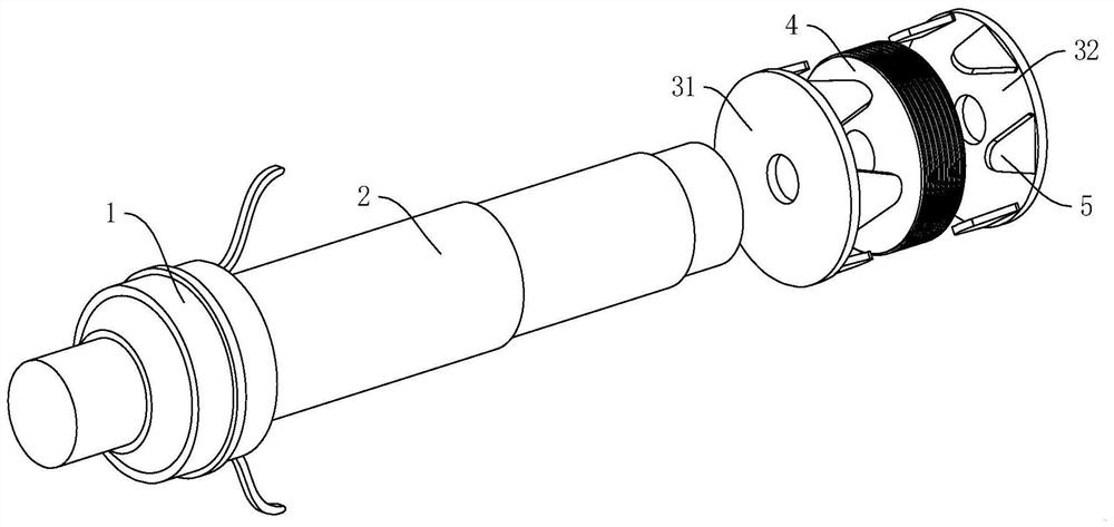
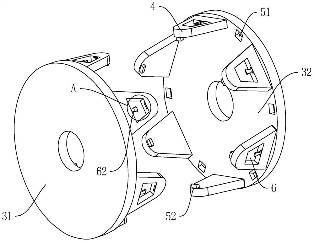
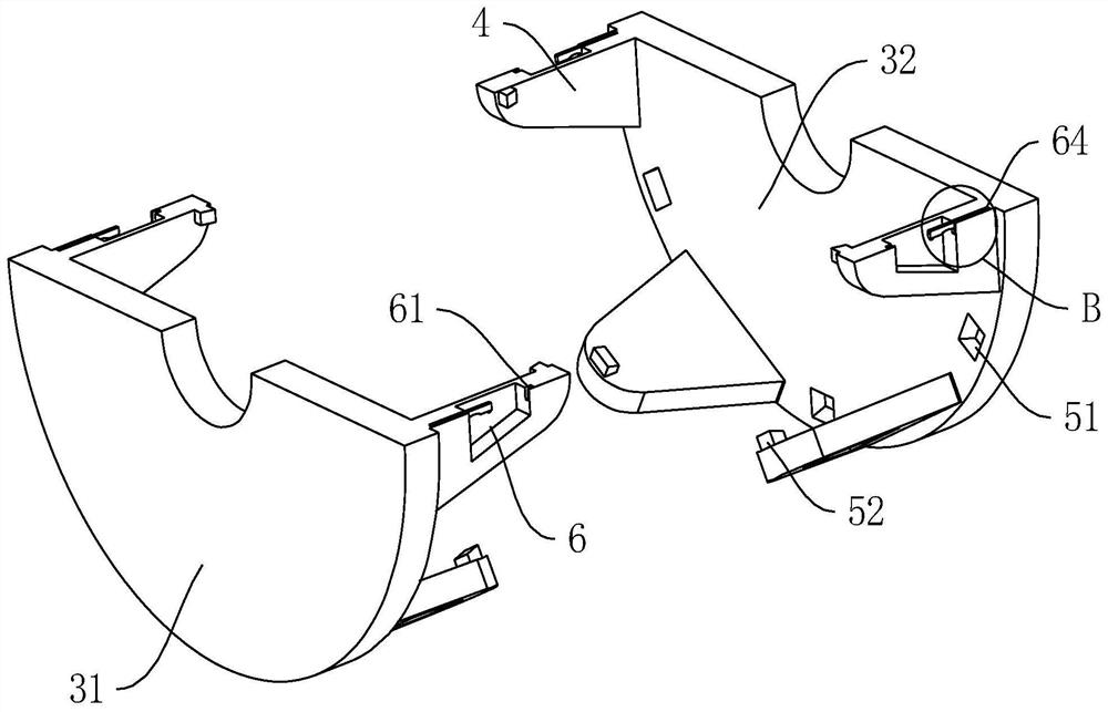
[0019] like Figure 1-5 A self-excited single-phase generator shown, including a collector ring 1, a rotor shaft 2, a front claw pole 31, a rear claw pole 32, a magnetic yoke 4 and a claw pole finger 5, a front claw pole 31 and a rear claw pole 32 The size of the upper cl...


PUM


Abstract

The invention discloses a self-excited single-phase generator, in particular to the technical field of excitation generators, comprising a collector ring, a rotor shaft, a front claw pole, a rear claw pole, a magnetic yoke and a claw pole finger. The size of the claw pole fingers on the rear claw pole decreases in turn along the direction of the two opposite faces, and a spacing groove matching the size of the claw pole fingers is arranged between each two claw pole fingers. The claw pole fingers on the claw pole are provided with connecting grooves and connecting plates for connecting the opposite ends of the two upper claw pole fingers. In the present invention, by installing the opposite ends of the claw pole fingers on the front claw pole and the rear claw pole at a distance, the magnetic permeability generated by the permanent magnets on the claw pole fingers generates a magnetic permeability space in the spacing groove, thereby further ensuring that the permanent magnets are inverted conductors. There is no dead space in the space, and the stability of magnetic permeability; while making the permanent magnets in the claw pole fingers detachable and installing, it has better fixing strength than the traditional installation by directly attaching the permanent magnets to the claw pole fingers. and stability.

Description

technical field [0001] The present invention relates to the technical field of excitation generators, and more particularly, to a self-excited single-phase generator. Background technique [0002] The generator is a mechanical device that converts other forms of energy into electrical energy. The generator excitation system is a general term for the power supply and its auxiliary equipment that supply the excitation current of the synchronous generator. It generally consists of two main parts, the excitation power unit and the excitation regulator. [0003] The current self-excited single-phase generator rotors have permanent magnets embedded between the front and rear claw poles to increase the magnetic permeability of the claw poles. However, the position of the permanent magnets is unstable and directly affects the performance of the product, increasing the difficulty of assembly. SUMMARY OF THE INVENTION [0004] In order to solve the above technical problems, the pre...

Claims


Application Information

Patent Timeline
Patent Type & Authority Patents(China)
IPC IPC(8): H02K1/24H02K1/28H02K1/2713H02K19/28H02K21/12
CPCH02K1/243H02K1/28H02K1/27H02K19/28H02K21/12
Inventor 王远锋石斌
Owner 安徽德科电气科技有限公司
Why Eureka
Try Eureka