Object edge noise reduction method and system for infrared image

A technology of infrared image and noise reduction system, applied in the field of image processing

Pending Publication Date: 2020-10-20
FOSHAN UNIVERSITY
View PDF4 Cites 0 Cited by
  • Summary
  • Abstract
  • Description
  • Claims
  • Application Information

AI Technical Summary

Problems solved by technology

[0003] The purpose of the present invention is to provide a method and system for object edge noise reduction of infrared...

Method used


Image

  • Object edge noise reduction method and system for infrared image
  • Object edge noise reduction method and system for infrared image
  • Object edge noise reduction method and system for infrared image

Examples


Embodiment Construction

[0030] This part will describe the specific embodiment of the present invention in detail, and the preferred embodiment of the present invention is shown in the accompanying drawings. Each technical feature and overall technical solution of the invention, but it should not be understood as a limitation on the protection scope of the present invention.

[0031] In the description of the present invention, it should be understood that the orientation descriptions, such as up, down, front, back, left, right, etc. indicated orientations or positional relationships are based on the orientations or positional relationships shown in the drawings, and are only In order to facilitate the description of the present invention and simplify the description, it does not indicate or imply that the device or element referred to must have a specific orientation, be constructed and operated in a specific orientation, and thus should not be construed as limiting the present invention.

[0032] I...


PUM


Abstract

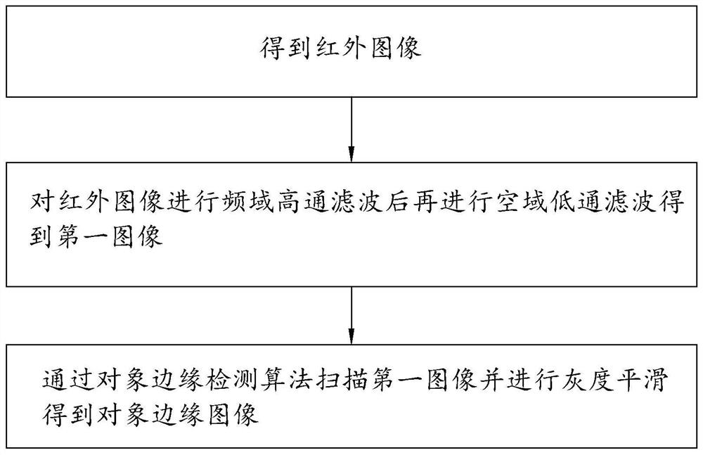
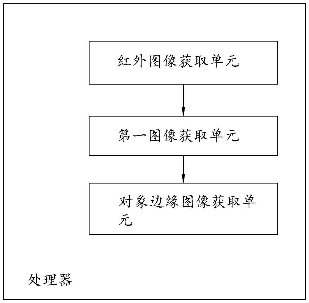
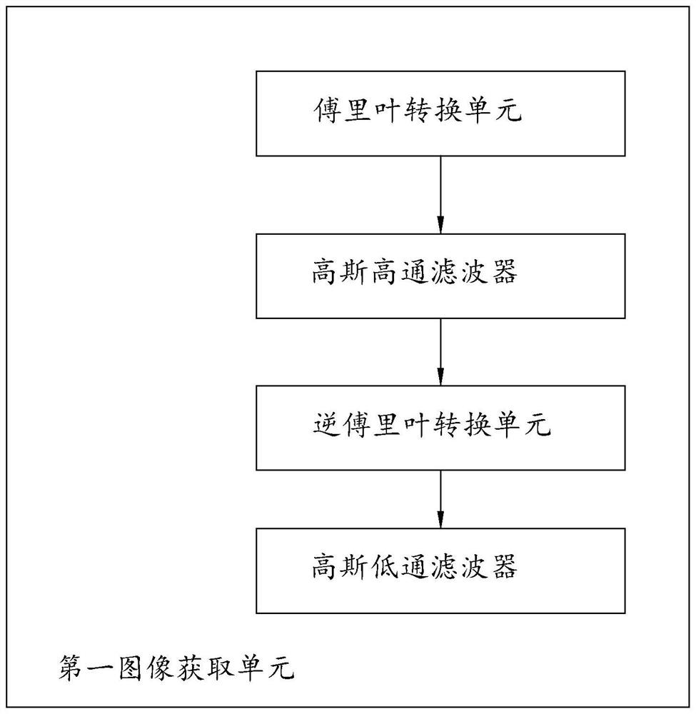
The invention discloses an object edge noise reduction method and a system for an infrared image. The method comprises the steps that step 1, obtaining the infrared image; step 2, carrying out frequency domain high-pass filtering on the infrared image and then carrying out spatial domain low-pass filtering to obtain a first image; and step 3, scanning the first image through an object edge detection algorithm and carrying out gray-scale smoothing to obtain an object edge image. The system comprises an infrared image acquisition unit, a first image acquisition unit and an object edge image acquisition unit. The method is mainly used in the technical field of image processing.

Description

technical field [0001] The present invention relates to the technical field of image processing, in particular to a method and system for reducing noise of an object edge of an infrared image. Background technique [0002] Biological images or thermal imaging images of other heat-generating entities acquired by infrared image acquisition equipment are relatively common, and its collision detection is a common problem. For areas with certain dangers such as lakes, hills and areas with potential subsidence, or buildings with confidentiality requirements, in order to prevent unintentional entry of unintentional personnel, it is often necessary to set up corresponding infrared monitoring equipment to monitor them around the clock. monitor. Such infrared monitoring equipment is often just a number of ordinary cameras set up on the periphery of the monitored area. In the control room, the monitoring personnel use the video data fed back by multiple cameras in real time to confir...

Claims


Application Information

Patent Timeline
IPC IPC(8): G06T5/00G06T7/13G06T7/136
CPCG06T5/002G06T7/13G06T7/136G06T2207/10048G06T2207/20056G06T2207/20192
Inventor 张彩霞胡绍林王向东王斯琪
Owner FOSHAN UNIVERSITY
Why Eureka
Try Eureka