Electric vehicle wireless charging method and system based on intelligent lamp pole

An electric vehicle, wireless charging technology, applied in electric vehicle charging technology, electric vehicles, charging stations, etc., can solve the problems of easy leakage or short circuit, waste of space, unsatisfactory safety performance, etc., to achieve good safety and stability Effect

Active Publication Date: 2020-10-16
深圳联和智慧科技有限公司
View PDF6 Cites 0 Cited by
  • Summary
  • Abstract
  • Description
  • Claims
  • Application Information

AI Technical Summary

Problems solved by technology

In this method, firstly, the charging connector is exposed, which is prone to leakage or short circuit in rainy days, and the safety performance is not satisfactory; secondly, sufficient space is required for use, and the waste of space is serious

Method used


Image

  • Electric vehicle wireless charging method and system based on intelligent lamp pole
  • Electric vehicle wireless charging method and system based on intelligent lamp pole
  • Electric vehicle wireless charging method and system based on intelligent lamp pole

Examples


Embodiment 1

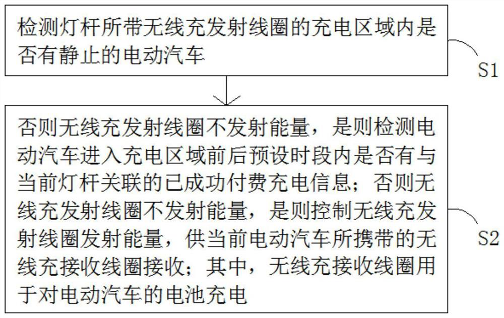
[0021] An embodiment of the present invention provides a wireless charging method for an electric vehicle based on a smart light pole, such as figure 1 shown, including the following steps:

[0022] Step S1: Detect whether there is a stationary electric vehicle in the charging area of ​​the wireless charging transmitter coil attached to the light pole.

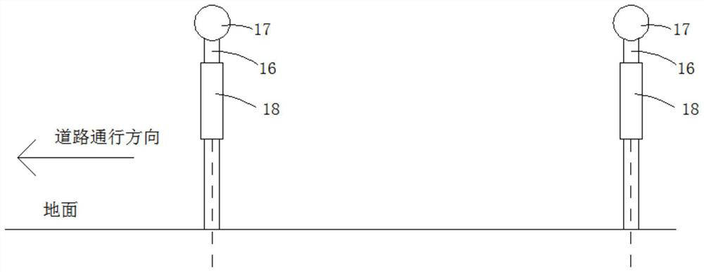
[0023] In this embodiment, before the step of detecting whether there is a stationary electric vehicle, two sets of detection rods are arranged horizontally in the charging area of ​​the wireless charging transmitting coil carried by the light pole; A rubber head in contact with the bottom of the electric vehicle is fixed; a tilt switch with the detection end facing directly downward is also fixed on the side surface of the detection rod. Specifically, when an electric vehicle enters the charging area of ​​the wireless charging transmitter coil on the light pole, the detection rod will tilt downward under the push of the elec...

Embodiment 2

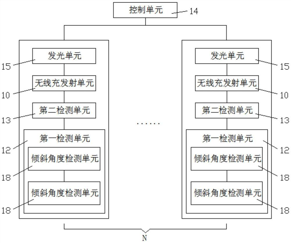
[0031] An embodiment of the present invention provides a wireless charging system for an electric vehicle based on a smart light pole, based on the wireless charging method for an electric vehicle based on a smart light pole provided in Embodiment 1, such as Figure 2-Figure 3 As shown, the system includes:

[0032] The wireless charging and transmitting unit 10 is set on the light pole;

[0033] A wireless charging and receiving unit (not shown in the figure), located on the electric vehicle;

[0034] The first detection unit 12 is used to detect whether there is a stationary electric vehicle in the charging area of ​​the wireless charging and transmitting unit 10 carried by the light pole;

[0035] The second detection unit 13 is used to detect whether there is successful paid charging information associated with the current light pole within a preset period of time before and after the electric vehicle enters the charging area;

[0036] A control unit 14, configured to co...


PUM


Abstract

The invention relates to an electric vehicle wireless charging method and system based on an intelligent lamp post. The method comprises the steps: whether a static electric vehicle exists in a charging area of a wireless charging transmitting coil arranged on a lamp post or not is detected, if not, the wireless charging transmitting coil does not transmit energy, and if so, whether successfully paid charging information associated with the current lamp post exists in a preset time period before and after the electric vehicle enters the charging area or not is detected; and if not, the wireless charging transmitting coil does not transmit energy, and if so, the wireless charging transmitting coil is controlled to transmit energy for a wireless charging receiving coil of the current electric automobile to receive. An owner of the electric automobile can be charged without getting off the automobile, so that time and labor are saved; an exposed charging connector is avoided, so that weather interference is avoided, and good safety and stability are achieved; and meanwhile, a plurality of electric automobiles in the same range can be charged in turn under one lamp post, and space waste is avoided.

Description

technical field [0001] The present invention relates to the technical field of vehicle charging, and more specifically, to a wireless charging method and system for electric vehicles based on smart light poles. Background technique [0002] Electric vehicles refer to vehicles powered by on-board power supplies, which are more environmentally friendly than fuel vehicles. However, when using it, how to charge it in time to ensure a good battery life has become a key consideration. Now it is mostly to find a specific site to install a batch of charging piles, divide the charging parking spaces, and charge electric vehicles through wired methods. In this method, firstly, the charging connector is exposed, which is prone to leakage or short circuit in rainy days, and the safety performance is not satisfactory; secondly, sufficient space is required for use, and the space waste is serious. Contents of the invention [0003] The technical problem to be solved by the present inv...

Claims


Application Information

Patent Timeline
Patent Type & Authority Applications(China)
IPC IPC(8): B60L53/126B60L53/66H02J50/10H02J50/80
CPCB60L53/126B60L53/665H02J50/10H02J50/80Y02T90/16
Inventor 杨海赖晓俊吴剑平唐盼王鹏林海荣
Owner 深圳联和智慧科技有限公司
Why Eureka
Try Eureka