
Foundation pit monitoring device for high-rise buildings

A technology for engineering monitoring and high-rise buildings, applied in basic structure engineering, construction, basic structure tests, etc., can solve problems such as poor flexibility, time-consuming, and non-adjustable angles, achieve high precision, save energy, and improve accuracy Effect

Inactive Publication Date: 2020-10-13
卢伟锦
View PDF0 Cites 11 Cited by
  • Summary
  • Abstract
  • Description
  • Claims
  • Application Information

AI Technical Summary

Problems solved by technology

[0002] At present, the horizontal displacement monitoring device and the vertical displacement monitoring device commonly used in engineering are installed separately, with a single structure and poor flexibility. The horizontal displacement is to fix the prism at the place to be monitored through a fixed connection. Manual lifting is required for vertical displacement monitoring, which takes a lot of time and cannot guarantee the accuracy of monitoring data. Therefore, we propose a foundation pit engineering monitoring device for high-rise buildings

Method used


Image

  • Foundation pit monitoring device for high-rise buildings
  • Foundation pit monitoring device for high-rise buildings
  • Foundation pit monitoring device for high-rise buildings

Examples


Embodiment Construction

[0023] The following will clearly and completely describe the technical solutions in the embodiments of the present invention with reference to the accompanying drawings in the embodiments of the present invention. Obviously, the described embodiments are only some, not all, embodiments of the present invention. Based on the embodiments of the present invention, all other embodiments obtained by persons of ordinary skill in the art without making creative efforts belong to the protection scope of the present invention.

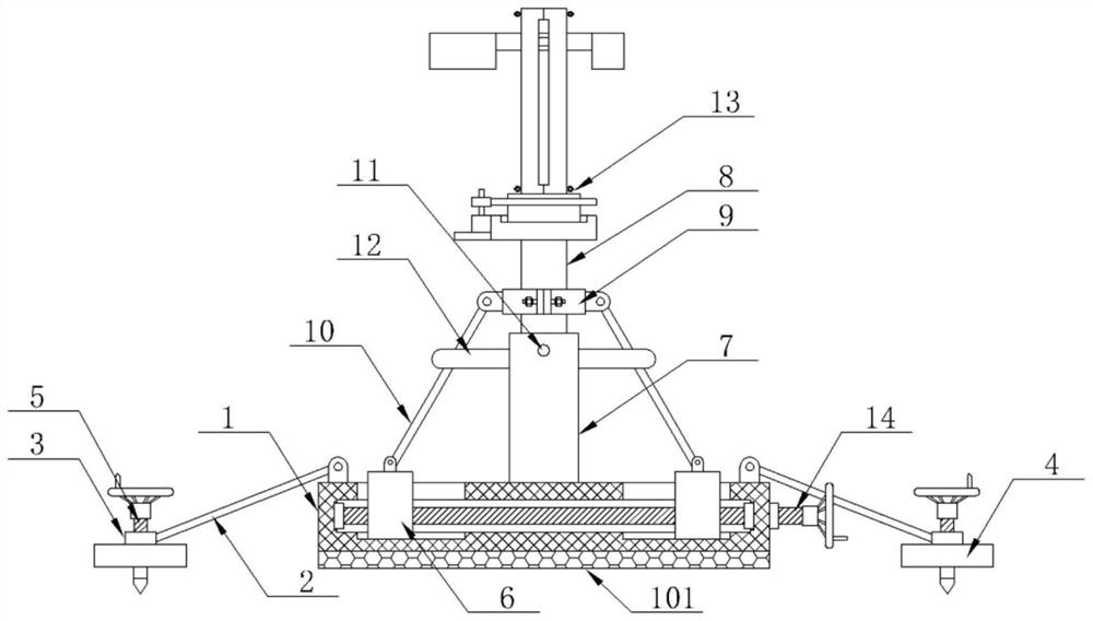
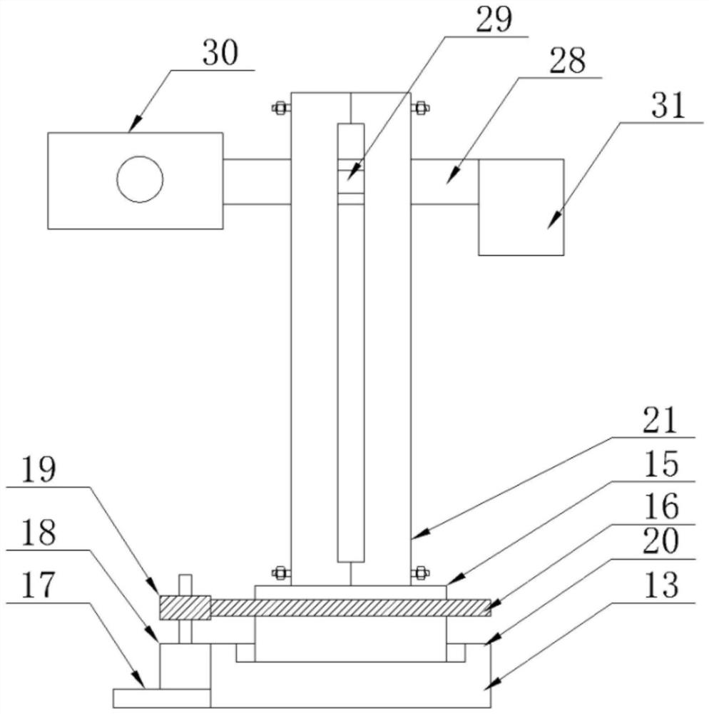
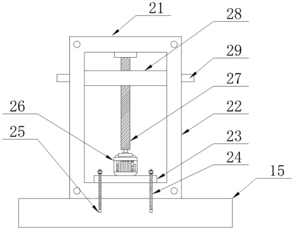
[0024] The present invention provides a technical solution: a foundation pit engineering monitoring device for high-rise buildings, please refer to figure 1 , including the base 1, the four corners of the top outer wall of the base 1 are equipped with a support rod 2 through a hinge, the other end of the support rod 2 is fixedly installed with a connecting pipe 3, and the bottom of the connecting pipe 3 is fixedly installed with a spacer 4, and the inside of th...


PUM


Abstract

The invention discloses a foundation pit monitoring device for high-rise buildings in the technical field of foundation pit engineering monitoring. The foundation pit monitoring device comprises a base, the top of a movable block extends to the outer wall of the top of the base, and an open groove matched with the movable block is formed in the outer wall of the top of the base. A main casing pipeis arranged at the center of the outer wall of the top of the base, and the top of the main casing pipe is movably connected with a lifting rod in an inserting mode. A screw rod is arranged at the top power end of a motor, a lifting plate is arranged on the outer wall of the screw rod in a sleeved mode through screw threads, and sliding blocks are arranged on the outer walls of the front side andthe rear side of the lifting plate. The motor can drive the screw rod to rotate. The screw rod rotates, so that the lifting plate can do lifting motion under the limit of the sliding blocks and the open groove to change the ground clearance of a monitor body, and thus multi-point monitoring in the vertical direction is carried out. A counterweight block can maintain the balance of the front end and the rear end of the lifting plate, and the monitor process can increase an external electric control box for control. No manual operation is needed, so physical strength is saved. Moreover, mechanical regulation is more accurate than manual regulation.

Description

technical field [0001] The invention relates to the technical field of foundation pit engineering monitoring, in particular to a foundation pit engineering monitoring device for high-rise buildings. Background technique [0002] At present, the horizontal displacement monitoring device and the vertical displacement monitoring device commonly used in engineering are installed separately, with a single structure and poor flexibility. The horizontal displacement is to fix the prism at the place to be monitored through a fixed connection. Manual lifting is required for vertical displacement monitoring, which takes a lot of time and cannot guarantee the accuracy of monitoring data. Therefore, we propose a foundation pit engineering monitoring device for high-rise buildings. Contents of the invention [0003] The object of the present invention is to provide a foundation pit engineering monitoring device for high-rise buildings to solve the problems raised in the above-mentioned...

Claims


Application Information

Patent Timeline
Patent Type & Authority Applications(China)
IPC IPC(8): F16M11/04F16M11/08F16M11/18F16M11/22E02D33/00E02D17/02
CPCE02D17/02E02D33/00F16M11/041F16M11/046F16M11/08F16M11/18F16M11/22
Inventor 卢伟锦
Owner 卢伟锦
Learn More