Flexible joint for railway vehicle braking system

A braking system, flexible joint technology, applied in the direction of pipe/pipe joint/pipe fitting, adjustable connection, branch pipeline, etc., can solve the problems of easy leakage, flange fastener pipeline leakage, etc., to achieve extended use The effect of longevity, reduction of verticality, cost saving of train inspection and factory repair

Active Publication Date: 2021-08-31
MEISHAN CRRC BRAKE SCI & TECH CO LTD
View PDF10 Cites 0 Cited by
  • Summary
  • Abstract
  • Description
  • Claims
  • Application Information

AI Technical Summary

Problems solved by technology

[0004] In order to solve the above-mentioned technical problem that the existing brake piping system is prone to leakage, the purpose of the present invention is to provide a flexible joint for the braking system of railway vehicles, which can realize the shortened gap of the brake piping system in a low temperature environment. Compensation to ensure that the pressure of the sealing ring remains unchanged and the sealing performance of the brake pipeline; it can effectively solve the technical problem that the flange fasteners are prone to loosening and cause pipeline leakage when the vehicle is under heavy load; it is easy to replace the vehicle The sealing ring between the connections of the brake piping system can effectively avoid replacing the sealing ring under the premise of cutting off the pipe hanger on the piping system, saving manpower, time and material costs

Method used


Image

  • Flexible joint for railway vehicle braking system
  • Flexible joint for railway vehicle braking system
  • Flexible joint for railway vehicle braking system

Examples


Embodiment 1

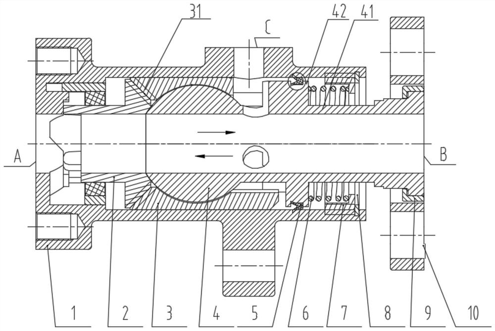
[0043] The embodiment is basically as Figure 1 to Figure 4 As shown: this embodiment provides a flexible joint for a railway vehicle braking system, including a flexible three-way body 1, a torsion bar assembly 2, a swivel joint body 4 and a flange body 10. Specifically, the left end of the flexible three-way body 1 has a second A connection surface A, the flexible three-way body 1 is connected to the brake main pipe on its left side through the first connection surface A; and the top side wall of the flexible three-way body 1 has a third connection surface C, and the flexible three-way body 1 passes through the third connection surface C It is connected with the branch gas path to form a flexible joint tee structure.

[0044] Such as figure 2 As shown, the torsion bar composition 2 provided in this embodiment is arranged in the flexible tee body 1 and close to the side of the first connecting surface A, and the torsion bar composition 2 is connected with the inner side wal...

Embodiment 2

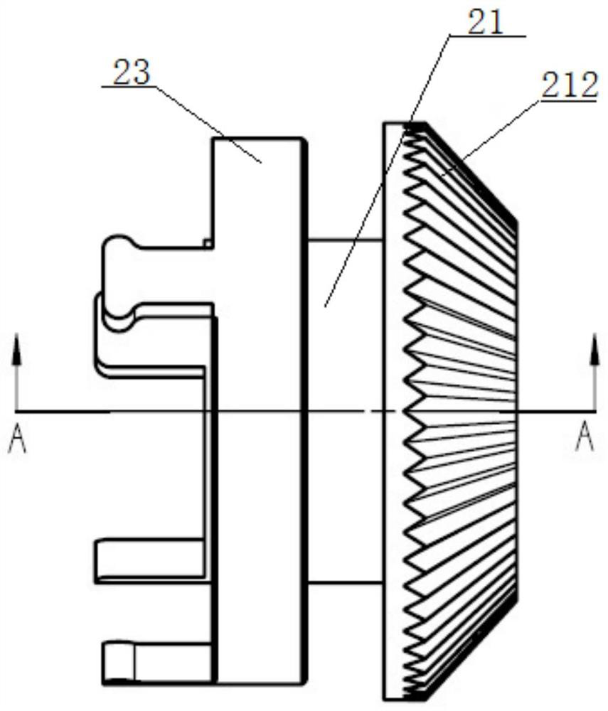
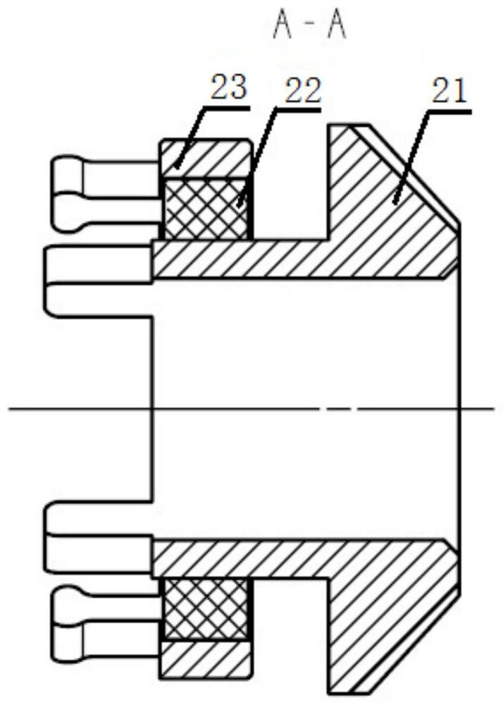
[0050] As a preferred embodiment of Embodiment 1, Embodiment 2 is basically the same as Embodiment 1, except that: please combine figure 2 with image 3 As shown, this embodiment provides a flexible joint for a railway vehicle braking system. Aiming at solving the technical problem that it is difficult to replace the sealing ring in vehicle train inspection, the torsion bar composition 2 provided by this embodiment includes a torsion bar 21, a torsion spring 22 and a The limiting outer ring 23 and the torsion spring 22 are arranged between the torsion bar 21 and the limiting outer ring 23, so that the torsion bar 21 and the limiting outer ring 23 can rotate relative to each other, so that the torsion bar 21 has a degree of freedom of rotation, It can also be reset under the action of the spring 6. Combined with the design of the rotary joint body 4, it can effectively meet the misalignment of the connection center of the adjacent brake pipe system, without affecting the seali...

Embodiment 3

[0056] As a preferred embodiment of Embodiment 2, Embodiment 3 is basically the same as Embodiment 2. The difference is that this embodiment provides a flexible joint for a railway vehicle braking system. In order to realize the flexible joint is easy to install and easy to manufacture, A spring holder 7 is provided on the inner side of the end of the flexible tee body 1 close to the spring 6. The spring holder 7 is fixedly connected with the inner wall of the flexible tee body 1, and the extension section 41 of the rotary joint body 4 has a direction perpendicular to the centerline of the brake pipe air circuit. The raised portion 42 of the spring 6 abuts against the raised portion 42 and the right end of the spring 6 against the spring holder 7 . With the above-mentioned structure, the spring holder 7 designed according to the spring 6 can effectively ensure its installation stability, and the design of the spring holder 7 can make the right end of the flexible tee body 1 hav...


PUM


Abstract

The invention discloses a flexible joint for a railway vehicle braking system, which relates to the technical field of railway vehicle braking devices; In the tee body, the torsion bar is connected with the inner wall of the flexible tee body in a limited fit. The outer side of the rotating joint body is provided with a ball sleeve and forms a spherical hinge connection with the ball sleeve. The ball sleeve forms a cylindrical fit with the inner wall of the flexible tee body. connection, the transmission connection is realized between the torsion bar composition and the ball sleeve, the flange body is installed on the extension section of the swivel joint body, and the spring is located between the extension section of the swivel joint body and the end face of the flexible tee body; by implementing this technical scheme, it can Effectively solve the technical problem that the existing brake pipe system is prone to leakage, ensure the sealing performance of the brake pipe system, reduce the requirements for the perpendicularity between the brake pipe system and the flange, and be easy to manufacture; at the same time, it is convenient to replace the vehicle brake pipe system The sealing ring between the connections has a good application prospect.

Description

technical field [0001] The invention relates to the technical field of railway vehicle braking devices, and more specifically, relates to a flexible joint for a railway vehicle braking system. Background technique [0002] The brake system is the safety guarantee for the safe and reliable operation of railway vehicles. The brake pipe system of railway vehicles in my country is widely used to connect and seal with flange fasteners. It mainly bears the horizontal longitudinal impact force and the vertical load, so the brake pipe will deflect and vibrate with the chassis. [0003] In view of the low-temperature leakage of railway vehicles in low-temperature areas in northern my country, the low-temperature leakage of freight cars has long plagued vehicle safety and affected transportation efficiency. With the underframe deflecting and vibrating, it becomes loose, which in turn leads to the leakage of the brake piping system; on the one hand, due to time constraints, train inspec...

Claims


Application Information

Patent Timeline
Patent Type & Authority Patents(China)
IPC IPC(8): F16L27/073F16L27/053F16L27/107F16L41/18
CPCF16L27/053F16L27/073F16L27/107F16L41/18
Inventor 肖八励刘保华李果杨璨田宇刘毅杨建平申燕飞宋志勇
Owner MEISHAN CRRC BRAKE SCI & TECH CO LTD
Why Eureka
Try Eureka