


Quick Research
Generate reliable direction feasibility study reports for your R&D in just a few steps.

Technical Q&A
Discover and master advanced knowledge NOW. Basics, ideas, possibilities, all at once.

Find Solutions
As an expert in R&D theories, this can generate solutions to your technical problems instantly.

Evaluate Feasibility
Analyze your overall solution with one click, know your potential R&D risks in advance.

Monitor Landscape
Get weekly tech updates, stay abreast of the latest tech innovations and key insights.
Partitioned joint control purification system for plant dust treatment
A purification system and plant technology, applied in heating and ventilation control systems, air conditioning systems, ventilation systems, etc., can solve problems such as smoke and dust control problems, and achieve the effect of ensuring air freshness, low system pressure loss, and small footprint
- Summary
- Abstract
- Description
- Claims
- Application Information
AI Technical Summary
Problems solved by technology
Method used
Image

Examples
Embodiment 1
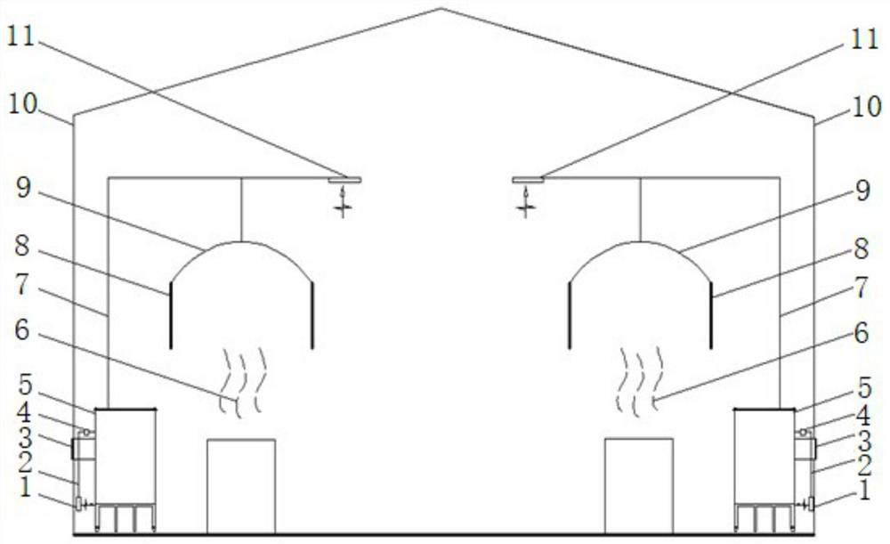
[0040] see figure 1 with figure 2 , the partition linkage control and purification system in the illustration is a specific embodiment of the present invention. In this embodiment, the interior of the factory building 10 is divided into several dust-producing areas, and each dust-producing area is provided with an air processing unit 12. Each air processing unit 12 It can be opened by joint control, or partially or fully opened by manual control, and the joint control and purification of each dust-producing area can be carried out.
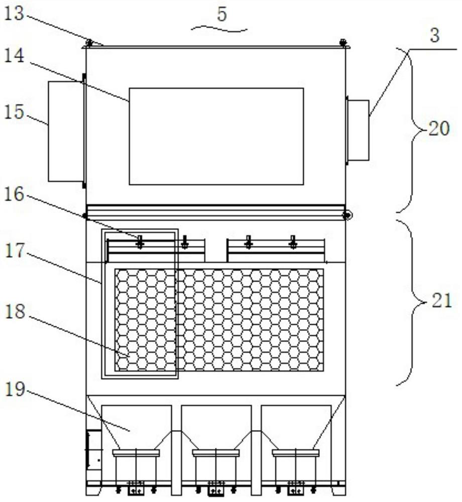
[0041] Specifically, the air processing unit includes a dust removal unit 5 and an air supply duct 2 and a return air duct 7 connected to the dust removal unit 5. The dust removal unit 5 is arranged inside the workshop to centrally process the dusty gas in the workshop. One end of the air supply duct 2 is It is connected to the air supply port 1 set inside the factory building 10, and the other end is connected to the dust removal unit 5. The ai...
Embodiment 2
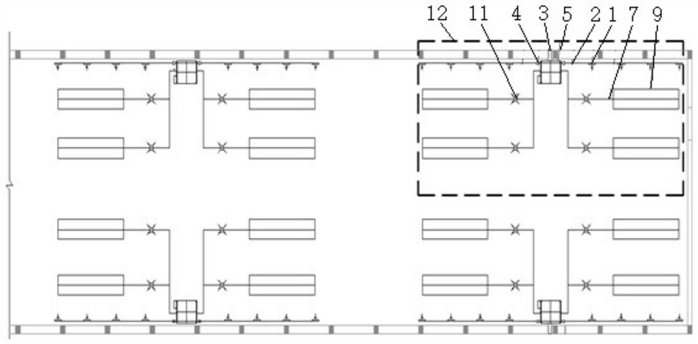
[0049] see Figure 5 with Image 6 , the partition linkage control and purification system in this embodiment is another specific embodiment of the present invention. The dust-producing areas inside the plant in this embodiment are relatively scattered and evenly distributed. After the interior of the plant is evenly divided into several dust-producing areas In this embodiment, the air handling unit 12 is evenly laid with return air ducts 7 on the top of the factory building, and a plurality of return air outlets 11 are evenly arranged on the return air ducts 7, and the return air in Embodiment 1 is replaced by a plurality of evenly arranged air return ducts. The wind hood evenly sucks the dust-laden airflow rising in the dust-producing area.
[0050] Other air supply ducts and dust removal units of the air handling unit 12 in this embodiment can refer to Embodiment 1, and this embodiment will not be repeated here.
[0051] The specific working process of Embodiment 1 and Em...
PUM
 Abstract
Description
Claims
Application Information
 - R&D Engineer
- R&D Manager
- IP Professional
- Industry Leading Data Capabilities
- Powerful AI technology
- Patent DNA Extraction
Browse by: Latest US Patents, China's latest patents, Technical Efficacy Thesaurus, Application Domain, Technology Topic, Popular Technical Reports.
© 2024 PatSnap. All rights reserved.Legal|Privacy policy|Modern Slavery Act Transparency Statement|Sitemap|About US| Contact US: help@patsnap.com