


Quick Research
Generate reliable direction feasibility study reports for your R&D in just a few steps.

Technical Q&A
Discover and master advanced knowledge NOW. Basics, ideas, possibilities, all at once.

Find Solutions
As an expert in R&D theories, this can generate solutions to your technical problems instantly.

Evaluate Feasibility
Analyze your overall solution with one click, know your potential R&D risks in advance.

Monitor Landscape
Get weekly tech updates, stay abreast of the latest tech innovations and key insights.
A method for in-position and demoulding of the inner formwork of a concrete pipe gallery
A concrete and inner mold technology, which is applied in the fields of formwork/formwork/work frame, on-site preparation of building components, construction, etc. problem, to prevent the equipment from breaking and enhance the strength
- Summary
- Abstract
- Description
- Claims
- Application Information
AI Technical Summary
Problems solved by technology
Method used
Image


Examples
Embodiment 1
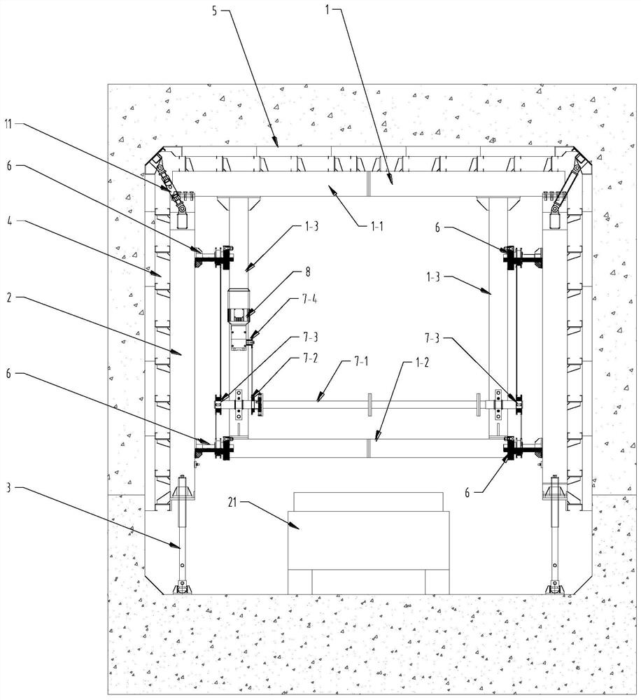
[0059] A mechanized equipment for the construction of a concrete pipe gallery, comprising: an inner mold formwork part and a lifting trolley part for moving the inner formwork formwork into place.
[0060] See attached Figure 1-5 , the mold base part of the internal mold includes a door frame 1, a movable column 2, a column lifting support leg 3, a side template 4, a top template 5, and a translation driver 6, a transmission assembly and a motor 8.
[0061] The door frame 1 is composed of the top door beam 1-1, the bottom cross brace 1-2 and the side vertical brace 1-3. The top door beam is made of H-shaped steel or steel plate tailor-welded into an H shape, and can be bolted by multiple sections. to meet the use of sections with different widths; the side vertical braces 1-3 are fixedly arranged between the top door beam 1-1 and the bottom cross brace 1-2, and play the role of connecting the top door beam and the bottom cross brace. A side vertical brace 1-3 is respectively...
Embodiment 2
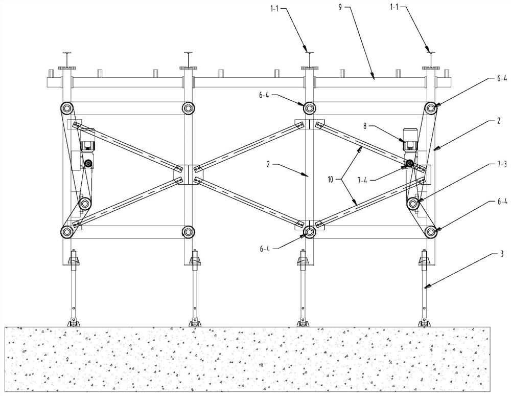
[0077] On the basis of Embodiment 1, further speaking, the inner mold frame can be longitudinally spliced into the required size by a plurality of inner mold frame units to adapt to different construction needs, and each inner mold frame unit can realize a motor 8 at the same time Drive eight translation drivers 6 to act synchronously. Two specific lectures: each internal mold frame unit includes two door frames 1, four movable columns 2, eight translation drivers 6, a motor 8 and a transmission shaft 7-1.
[0078] The two gantry frames are arranged longitudinally at intervals in the front and back, and a movable column is arranged on both sides of each gantry in the transverse direction (width direction). To stabilize the structure and prevent the inner mold formwork unit from being deformed by force, each movable column 2 is connected to the gantry part on its inner side through two translation drivers 6, that is, four translation drivers 6 are installed on each gantry 1; ...
Embodiment 3
[0080] On the basis of Embodiment 1, further, see the accompanying Figure 8 , the specific installation structure of the thrust bearing seat 6-3 and the rotating nut 6-2 of the translation driver 6 is: one end of the rotating nut 6-2 has a flange 6-21; the thrust bearing seat 6-3 includes The upper cover 6-31 and the base 6-32, the upper cover 6-31 and the base 6-32 are butted together by bolts, an installation cavity is formed between the upper cover 6-31 and the base 6-32, and the rotating nut 6- The flange 6-21 of 2 is installed in the installation cavity, and several turns are arranged between the upper surface of the flange 6-21 of the rotating nut 6-2 and the upper cover 6-31 of the thrust bearing seat 6-3. The ball 6-3a, the lower surface of the flange 6-21 of the rotating nut 6-2 and the base 6-32 of the thrust bearing seat 6-3 are also provided with some circles of balls 6-3b, the wing of the rotating nut 6-2 Several rings of balls 6-3c are also arranged between the...
PUM
 Abstract
Description
Claims
Application Information
 - R&D Engineer
- R&D Manager
- IP Professional
- Industry Leading Data Capabilities
- Powerful AI technology
- Patent DNA Extraction
Browse by: Latest US Patents, China's latest patents, Technical Efficacy Thesaurus, Application Domain, Technology Topic, Popular Technical Reports.
© 2024 PatSnap. All rights reserved.Legal|Privacy policy|Modern Slavery Act Transparency Statement|Sitemap|About US| Contact US: help@patsnap.com