Tube rail hoisting device

A technology of pipe rails and trolleys, which is applied in the direction of track systems, load suspension components, and running gears. It can solve the problems of running gear jams, cumbersome processes, and dust pollution, and achieves fast installation, high safety, and smooth operation. Caton effect

Active Publication Date: 2020-10-09
63653 FORCES PLA
View PDF8 Cites 0 Cited by
  • Summary
  • Abstract
  • Description
  • Claims
  • Application Information

AI Technical Summary

Problems solved by technology

At present, the application is relatively mature, and the installation and use methods are relatively simple, but there are still the following disadvantages: First, the main girder of the beam crane is generally an I-beam, and there is a risk of derailment when the traveling mechanism is turning or pulling sideways; If the traveling mechanism is exposed to the external environment for a long time, there will be dust pollution, blockage, etc., which will eventually cause the traveling mechanism to freeze and derail; third, when the length of the main beam is too long, multiple I-beam connections are required, and the alignment process is cumbersome

Method used


Image

  • Tube rail hoisting device
  • Tube rail hoisting device
  • Tube rail hoisting device

Examples


Embodiment Construction

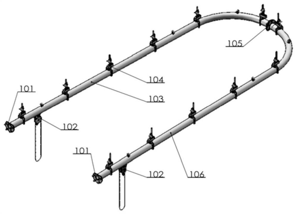
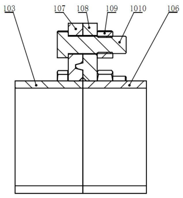
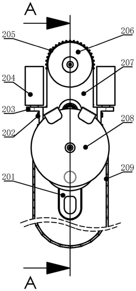
[0022] A pipe-rail crane, including a pipe rail, a ball wheel trolley, a limit flange, a connecting structure and a butt joint flange. The ball wheel trolley is mainly composed of two hemispherical wheels, two guide cylinders, two panels, a sprocket, and a gear combination Composed of structure and suspension ring, two hemispherical wheels are embedded in the pipe rail; the butt joint flange is a concave-convex flange connection structure, which is used to connect and fix the two sections of pipe rail; one side of the steel pipe is grooved, the section of the pipe rail is C-shaped, and the outer wall of the pipe rail passes through The connection structure is fixed to the rock wall or roof, the inner wall is used as the running track of the ball-wheel trolley, the outer wall of the pipe rail is fixed to the rock wall or roof through the connecting structure, and the inner wall is used as the running track of the ball-wheel trolley, and the ball-wheel trolley is mainly composed o...


PUM


Abstract

The invention relates to novel hoisting equipment, in particular to a tube rail hoisting device which is of an integrated hoisting structure combining a tube rail and a ball wheel trolley. The tube rail hoisting device includes the tube rail, the ball wheel trolley, limiting flanges, connecting structures and counter flanges; the tube rail is composed of a plurality of sections of straight groovedpipelines and curved grooved pipelines, and the sections are connected and fixed by the counter flanges; the tube rail is fixed to the tops of an adit or buildings such as a factory through the connecting structures; the ball wheel trolley is built in the tube rail; and the limiting flanges are installed to the outermost ends of the head and tail sections of the tube rail to limit the travel of the ball wheel trolley. The tube rail hoisting device is high in safety, low in cost and simple to install and operate, and can be widely used in various medium and small hoisting places, especially inhoisting operations of various underground projects.

Description

technical field [0001] The invention relates to a new type of hoisting equipment, in particular to a pipe rail crane, an integrated hoisting structure combined with a pipe rail and a ball wheel trolley. Background technique [0002] Single-girder cranes are mostly suitable for loading, unloading, and shipping of goods in workshops, warehouses, stockyards, and underground engineering environments. The main components are walking mechanisms and lifting mechanisms. At present, the application is relatively mature, and the installation and use methods are relatively simple, but there are still the following disadvantages: First, the main girder of the beam crane is generally an I-beam, and there is a risk of derailment when the traveling mechanism is turning or pulling sideways; If the traveling mechanism is exposed to the external environment for a long time, there will be dust pollution, blockage, etc., which will eventually cause the traveling mechanism to freeze and derail. ...

Claims


Application Information

Patent Timeline
Patent Type & Authority Applications(China)
IPC IPC(8): B66C7/04B66C7/08B66C9/02B66C9/08B66C9/14
CPCB66C7/04B66C7/08B66C9/02B66C9/08B66C9/14
Inventor 不公告发明人
Owner 63653 FORCES PLA
Why Eureka
Try Eureka