
Intelligent energy station

A technology of smart energy and new energy, applied in the field of smart energy stations, can solve the problems of not providing hydrogen energy vehicles, scattered supplementary energy facilities for new energy vehicles, and failing to realize long-term standardized management of charging systems, so as to improve energy utilization and facilitate The effect of normalized standardized management

Pending Publication Date: 2020-10-09
陈方红
View PDF0 Cites 2 Cited by
  • Summary
  • Abstract
  • Description
  • Claims
  • Application Information

AI Technical Summary

Problems solved by technology

[0004] However, the existing technology focuses on the construction of electric vehicle power supply system facilities, and cannot understand the charging status information in real time, cannot find fault points for maintenance in time, cannot stop or take corresponding preventive measures for man-made damage to facilities in time, and has not realized long-term standardized management of the charging system; Moreover, the existing technology does not provide gas supply facilities for hydrogen energy vehicles and liquid supply facilities for metal fuel vehicles, and cannot highly integrate new energy services, making the supplementary energy facilities for new energy vehicles scattered and messy, and increasing the difficulty of management of new energy vehicle service infrastructure

Method used


Image

  • Intelligent energy station
  • Intelligent energy station

Examples

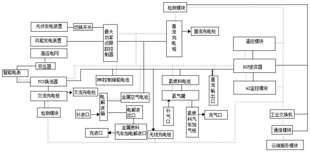

Embodiment Construction

[0023] In order to make the object, technical solution and advantages of the present invention clearer, the present invention will be further described in detail below in conjunction with the accompanying drawings and embodiments. It should be understood that the specific embodiments described here are only used to explain the present invention, not to limit the present invention.

[0024] To achieve the above object, the technical scheme of the present invention is as follows:

[0025] A smart energy station, including a new energy power generation module, an energy storage module, a charging module, a detection module, a communication module, and a cloud processing module, and the new energy power generation module is connected to the charging module, the energy storage module, the detection module, and the communication module , the energy storage module is connected to the charging module, the detection module and the communication module, the detection module is connected...


PUM


Abstract

The invention discloses an intelligent energy station, and relates to the field of new energy. The intelligent energy station provided by the invention comprises a new energy power generation module,an energy storage module, a charging module, a detection module, a communication module, a cloud processing module, an AI monitoring module, a temperature control module and a high-voltage power grid,and further comprises an inflation system and a liquid filling system. According to the invention, the state of the charging module is detected in real time, information of the charging module is collected, a fault point is found in time, the maintenance personnel can be informed and arranged in time for maintenance through the communication module and the cloud processing module, and normal operation of the energy station is guaranteed; the AI monitoring module in the intelligent energy station monitors the electric quantity use condition of the high-voltage power grid and monitors the electric quantity change condition of the system in real time, the energy storage module and the charging module can be powered through the power grid when the electric quantity of the power grid is sufficient, surplus power grid connection can be conducted when the electric quantity of the power generation module has surplus after meeting the charging module and the energy storage module, and the energy utilization rate is increased. The intelligent energy station provides a power charging, gas filling and electrolyte filling system, new energy automobile supplementary energy facilities are integrated together in a centralized mode, and normal standardized management of the intelligent energy station is facilitated.

Description

technical field [0001] The invention belongs to the field of charging and charging systems, and in particular relates to a smart energy station. Background technique [0002] Fossil energy is a non-renewable resource and also the most important industrial raw material. The combustion of fossil energy emits a large amount of harmful gas and dust, and vehicle exhaust is the chief culprit of urban air pollution. Electricity comes from a wide range of sources. New clean energy such as photovoltaics, wind power, and fuel cells generate electricity instead of burning fossil fuels. Pure electric vehicles instead of gasoline vehicles are the only way for future green transportation. Therefore, the promotion of new energy vehicles is crucial to saving non-renewable energy and protecting the environment. The promotion of new energy vehicles needs to solve the problem of charging and charging of new energy vehicles conveniently. Therefore, increasing the construction of charging and ...

Claims


Application Information

Patent Timeline
IPC IPC(8): B60L53/31B60L53/51B60L53/52B60L53/53B60L53/54B60L53/60B60S5/02H01M10/42H01M10/44H02J7/35
CPCB60S5/02B60L53/31B60L53/51B60L53/52B60L53/53B60L53/54B60L53/60H01M10/425H01M10/4285H01M10/441H01M2010/4271H01M2010/4278H02J7/35Y02E60/10Y02T10/70Y02T10/7072Y02T90/12Y02T90/16
Inventor 陈方红
Owner 陈方红
Learn More