
Rapid twisting and cutting equipment for building steel bars

A technology for building steel bars and cutting equipment, which is applied in chemical instruments and methods, cleaning methods and utensils, cleaning methods using gas flow, etc. problems, to achieve the effect of increasing the scope of application, convenient operation and improving efficiency

Inactive Publication Date: 2020-10-09
伍周睿
View PDF0 Cites 1 Cited by
  • Summary
  • Abstract
  • Description
  • Claims
  • Application Information

AI Technical Summary

Problems solved by technology

However, most of the equipment currently used for twisting and cutting steel bars is separate, and it is cumbersome to operate (because the steel bars need to be twisted first, and then the steel bars are moved to the cutting equipment); when the steel bars are twisted, the steel bars of different thicknesses cannot be kept stable; When cutting steel bars, cutting equipment cannot adjust the position of cutting steel bars, but requires personnel to manually adjust the position of steel bars

Method used


Image

  • Rapid twisting and cutting equipment for building steel bars
  • Rapid twisting and cutting equipment for building steel bars
  • Rapid twisting and cutting equipment for building steel bars

Examples


Embodiment Construction

[0023] The following will clearly and completely describe the technical solutions in the embodiments of the present invention with reference to the accompanying drawings in the embodiments of the present invention. Obviously, the described embodiments are only some, not all, embodiments of the present invention. Based on the embodiments of the present invention, all other embodiments obtained by persons of ordinary skill in the art without making creative efforts belong to the protection scope of the present invention.

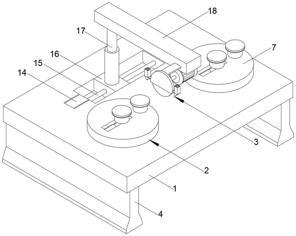
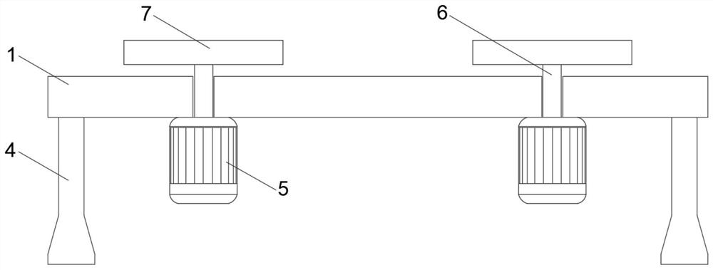
[0024] The present invention provides such as Figure 1-6 The shown one kind of fast torsion cutting equipment for building reinforcement comprises a support plate 1, two sets of torsion mechanisms 2 to maintain the level, a cutting mechanism 3 and two sets of legs 4 welded on both sides of the bottom wall of the support plate 1 respectively,

[0025] The torsion mechanism 2 of each group consists of a first motor 5 welded on the bottom wall of the support pla...


PUM


Abstract

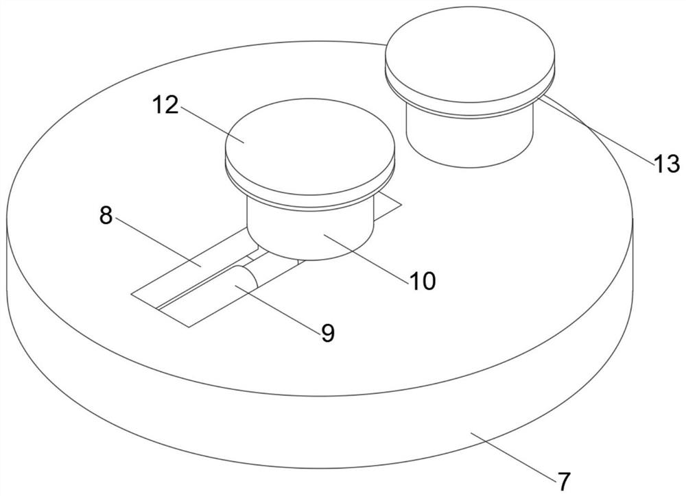
The invention discloses rapid twisting and cutting equipment for building steel bars. The rapid twisting and cutting equipment for the building steel bars includes a supporting plate, two groups of horizontally maintained twisting mechanisms, a cutting mechanism and two groups of supporting feet welded to two sides of the bottom wall of the supporting plate. Each group of twisting mechanisms is composed of first motors welded to the bottom wall of the supporting plate, first transmission shafts penetrating through the supporting plate and coaxially fixedly connected with crankshafts of the first motors and rotating discs welded and fixed to the top ends of the first transmission shafts, a group of accommodating grooves accommodating lead screws and the moving blocks are formed in the top wall of the supporting plate, and the lead screws penetrate through the moving blocks in the horizontal direction. According to the rapid twisting and cutting equipment for the building steel bars, therotating discs, an adjustment groove, an electric push rod and two groups of positioning blocks are arranged, so that the electric push rod is expanded and contracted to drive one group of positioning blocks to move to adjust the distance between the two groups of positioning blocks, the twisting mechanisms can fix the steel bars of different thicknesses, and the two groups of positioning blocksare used for enabling the twisting mechanisms to keep stable when the twisting mechanism fix the steel bars of different thicknesses.

Description

technical field [0001] The invention belongs to the technical field of steel bar processing, and in particular relates to a fast torsion cutting device for building steel bars. Background technique [0002] Steel bars are steel products used in the processing and production of reinforced concrete and prestressed reinforced concrete. Steel bars are used in various constructions that require concrete. Steel bars for reinforced concrete refer to straight or coiled steel for reinforced concrete reinforcement. Its shape is divided into two types: smooth round steel bars and deformed steel bars. The delivery status is Both straight and round. The light round steel bar is actually the small round steel and the disc circle of ordinary low carbon steel; the nominal diameter of the deformed steel bar is equivalent to the nominal diameter of the light round steel bar with the same cross section. [0003] In the construction industry, before steel bars are used, they often need to be ...

Claims


Application Information

Patent Timeline
Patent Type & Authority Applications(China)
IPC IPC(8): B21F7/00B21F11/00B08B5/02
CPCB08B5/02B21F7/00B21F11/00
Inventor 伍周睿
Owner 伍周睿
Learn More