Filter for treatment apparatus

A filter and equipment technology, applied in the field of centrifugal filter units, can solve problems such as unsolved problems, and achieve the effect of improving filtration

Active Publication Date: 2020-10-02
XEROS LTD
View PDF38 Cites 4 Cited by
  • Summary
  • Abstract
  • Description
  • Claims
  • Application Information

AI Technical Summary

Problems solved by technology

However, US 6,820,446 B2 does not address the problem of removing substrate-derived solid waste fibers and particles from tr...

Method used


Image

  • Filter for treatment apparatus
  • Filter for treatment apparatus
  • Filter for treatment apparatus

Examples


Embodiment Construction

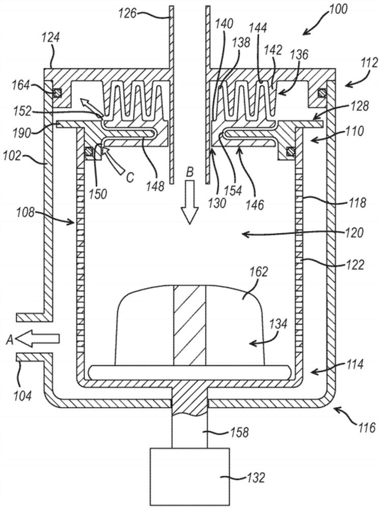
[0256] figure 1 A centrifugal filter unit (100) according to the invention is shown. The centrifugal filter unit (100) includes a housing (102) having an outlet (104) to enable filtered treatment formulation (shown by arrow A) to exit the centrifugal filter unit (100) through the outlet. The centrifugal filter unit (100) includes a filter (108) rotatably mounted in a housing (102). The filter (108) has a first end (110) proximate the first end (112) of the housing (102). The filter has a second end (114) proximate to a second end (116) of the housing (102). The filter has a sidewall (118) disposed between the first end (110) and the second end (114), with perforations (122) formed in the sidewall (118). The centrifugal filter unit (100) has a filter chamber (120). A cover (128) is located at the first end (110) of the filter. The cover (128) has a hole (130) that can be used to position the inlet (126) formed on the end cap (124), but the cover (128) substantially seals ...


PUM


Abstract

A centrifugal filter unit for an apparatus, wherein the apparatus is for use in the treatment of a substrate with a treatment formulation, the centrifugal filter unit comprising; a) a housing having an outlet configured to allow a filtrate to exit the centrifugal filter unit; b) a filter rotatably mounted in the housing, wherein the filter comprises a first end proximate a first end of the housing, a second end proximate a second end of the housing and a side wall connecting the first end of the filter and the second end of the filter, wherein the first end, second end and side wall of the filter define a filter chamber, and wherein the side wall comprises perforations configured to allow liquid to pass through but to prevent solid material from passing through; c) a lid configured to substantially seal the first end of the housing; d) an inlet configured to allow a feed to enter the filter chamber; e) a cap at the first end of the filter, wherein the cap comprises an aperture that cooperates with the inlet to allow the feed to enter the filter chamber; f) a drive means for rotating the filter; and g) an impeller, wherein the impeller is comprised in the filter chamber; wherein thecentrifugal filter unit is configured such that when the impeller rotates, the feed is drawn in to the filter chamber through the inlet and liquid is expelled through the perforations.

Description

technical field [0001] The present disclosure relates to a centrifugal filter unit for use in a treatment plant for treating substrates, in particular textile substrates or substrates comprising textiles, with a treatment formulation, and to a treatment plant comprising said filter comprising . The present disclosure also relates to methods of filtering formulations and methods of treating substrates. Background technique [0002] Traditional methods of treating and cleaning textiles and fabrics often involve aqueous cleaning using large volumes of water. These methods typically involve immersing the fabric in water followed by removal of the contaminant, suspending the aqueous contaminant and rinsing with water. The use of solid particles to improve and optimize these conventional methods is known in the art. For example, PCT patent publication WO2007 / 128962 discloses a method of cleaning soiled substrates using a variety of solid particles. Other PCT patent publication...

Claims


Application Information

Patent Timeline
IPC IPC(8): B01D33/11C02F1/00B01D33/72D06F39/10D06F33/47
CPCA47L15/4208B01D33/11B01D33/466B01D33/722B01D33/727C02F1/001D06F39/085D06F39/10C02F2103/002C02F2307/12D06F33/47B01D2201/325
Inventor 加雷思·埃文·林恩·琼斯
Owner XEROS LTD
Why Eureka
Try Eureka