
A power dispatching method and system for grid-connected renewable energy

A renewable energy and power dispatching technology, applied in energy storage, AC network circuits, electrical components, etc., can solve the problems of energy storage system life reduction, poor economy, and calculation delays, so as to improve economy, cooperate efficiently, and promote penetration effect

Active Publication Date: 2021-09-28
SHANDONG UNIV
View PDF6 Cites 0 Cited by
  • Summary
  • Abstract
  • Description
  • Claims
  • Application Information

AI Technical Summary

Problems solved by technology

[0005] The low-pass filter method and the spectral analysis method are dedicated to processing high-frequency fluctuations into low-frequency fluctuations, without considering the cooperation with power dispatching agencies, and these two methods are not applicable due to their own characteristics of phase delay and calculation delay. Large-area grid connection of renewable energy
[0006] The average power method meets the requirements of the current power dispatching organization, but during operation, the life of the energy storage system is often reduced due to frequent charging and discharging. Although it can be used for large-area grid-connected renewable energy, the economy is poor
[0007] The maximum-minimum power method is committed to improving the economics of the energy storage system, but it cannot take into account the coordination with the power dispatching organization, nor is it suitable for large-scale grid connection of renewable energy
[0008] It can be seen that none of these methods can achieve the grid-connected scheduling goals of efficient cooperation with power dispatching agencies and high energy storage system economy at the same time.

Method used


Image

  • A power dispatching method and system for grid-connected renewable energy
  • A power dispatching method and system for grid-connected renewable energy
  • A power dispatching method and system for grid-connected renewable energy

Examples


Embodiment Construction

[0034] It should be noted that the following detailed description is exemplary and intended to provide further explanation of the present invention. Unless defined otherwise, all technical and scientific terms used herein have the same meaning as commonly understood by one of ordinary skill in the art to which this invention belongs.

[0035] It should be noted that the terminology used here is only for describing specific embodiments, and is not intended to limit exemplary embodiments according to the present invention. As used herein, unless the context clearly dictates otherwise, the singular is intended to include the plural, and it should also be understood that when the terms "comprising" and / or "comprising" are used in this specification, they mean There are features, steps, operations, means, components and / or combinations thereof.

[0036] In the case of no conflict, the embodiments and the features in the embodiments of the present invention can be combined with eac...


PUM


Abstract

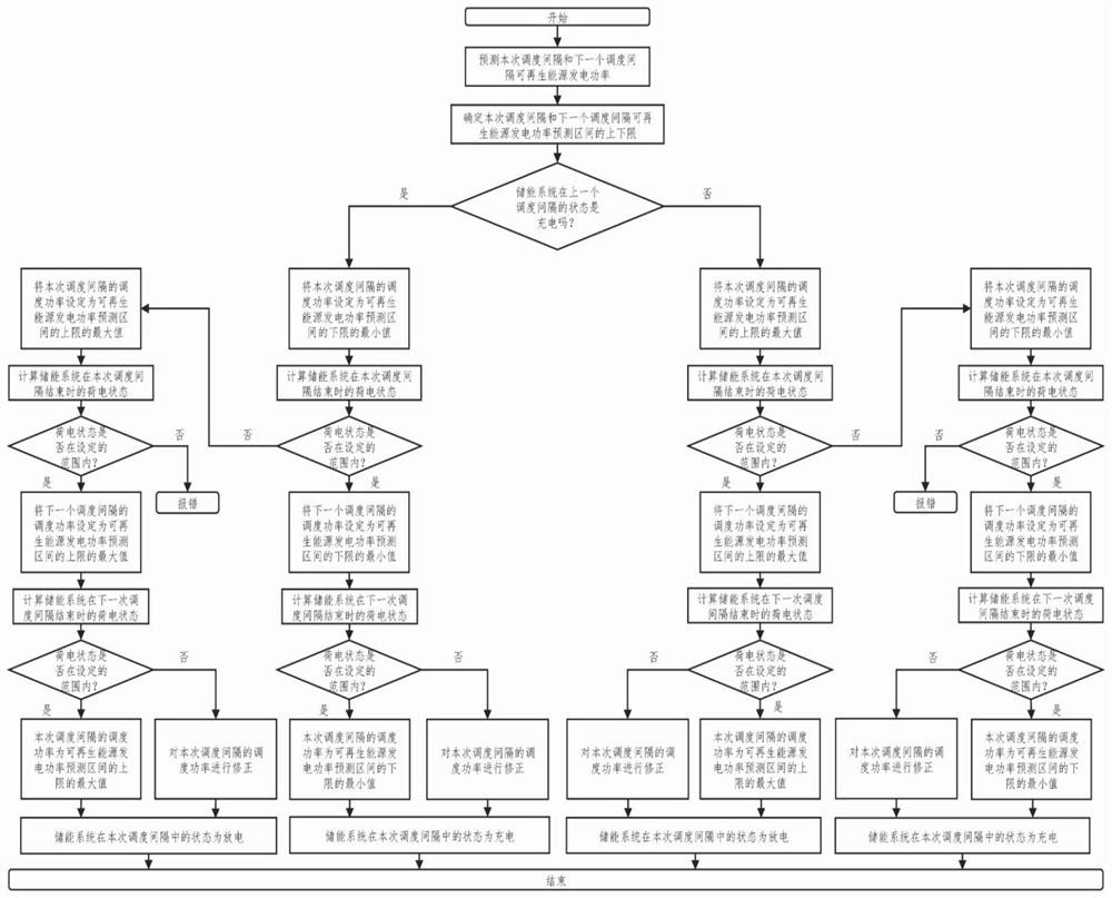
The invention discloses a power scheduling method and system for grid-connected renewable energy, including: power and scheduling interval based on forecasted renewable energy, and charging and discharging state and state of charge of the energy storage system in the last scheduling interval , to set the grid-connected power of renewable energy in the current scheduling interval; to predict the state of charge of the energy storage system, based on the set power of grid-connected renewable energy and the predicted state of charge of the energy storage system, the charge and discharge state of the energy storage system Control and adjust the grid-connected power of the previous scheduling interval when the energy storage system is charged and discharged, so that the energy storage system always operates between the set states of charge. Utilize the energy storage system to adjust the volatility and uncertainty of renewable energy, realize efficient cooperation with power dispatching organizations and economic utilization of the energy storage system, thereby promoting the penetration of renewable energy in the energy system.

Description

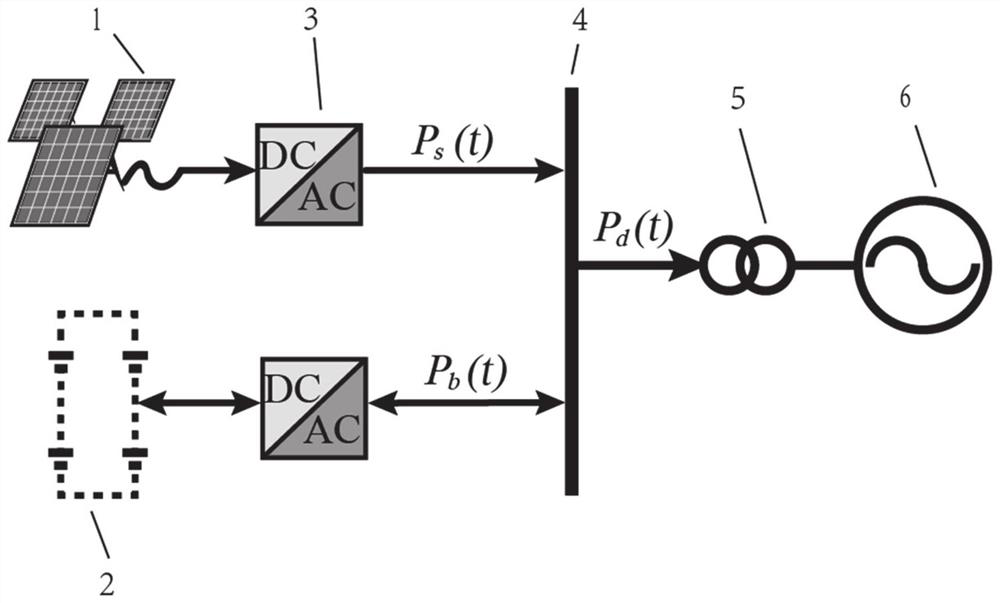
technical field [0001] The invention belongs to the technical field of power dispatching, and in particular relates to a power dispatching method and system for grid-connected renewable energy. Background technique [0002] The statements in this section merely provide background information related to the present disclosure and do not necessarily constitute prior art. [0003] With the rapid growth of electricity demand and the global joint response to climate change, the green and low-carbon transformation of energy has become a consensus. In the future, the main body of global energy supply will continue to transition to non-fossil energy, and renewable energy will accelerate to become the main body of energy growth. However, due to the influence of natural and climatic conditions, renewable energy often has the characteristics of high uncertainty and large fluctuation (or intermittency). These characteristics pose great challenges to the planning and operation of power ...

Claims


Application Information

Patent Timeline
Patent Type & Authority Patents(China)
IPC IPC(8): H02J3/38H02J3/28
CPCH02J3/28H02J3/381H02J2203/20H02J2300/20Y02E70/30
Inventor 孙锲王伟袁宝强马翠萍杜慕
Owner SHANDONG UNIV
Learn More