Battery core continuous winding device and battery core continuous winding method

A winding device and cell technology, applied to non-aqueous electrolyte batteries, circuits, electrical components, etc., can solve the problem of low winding efficiency

Inactive Publication Date: 2020-10-02
GEESUN AUTOMATION TECH
View PDF4 Cites 2 Cited by
  • Summary
  • Abstract
  • Description
  • Claims
  • Application Information

AI Technical Summary

Problems solved by technology

[0004] However, in the existing battery winding equipment, the battery winding auxiliary time (the time other than the winding time in the winding work) is generally longer than the winding time, and its winding efficiency is low

Method used


Image

  • Battery core continuous winding device and battery core continuous winding method
  • Battery core continuous winding device and battery core continuous winding method
  • Battery core continuous winding device and battery core continuous winding method

Examples


no. 1 example

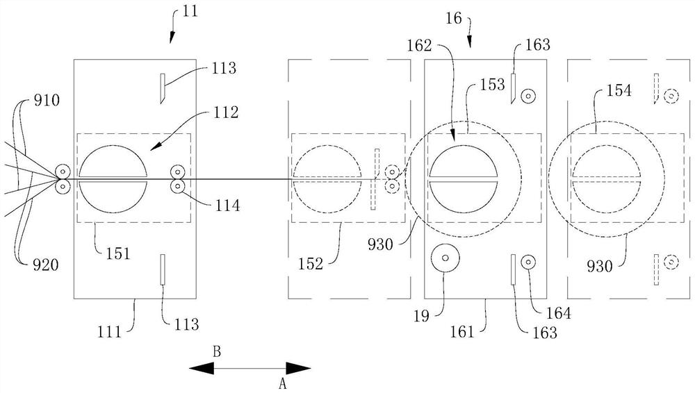
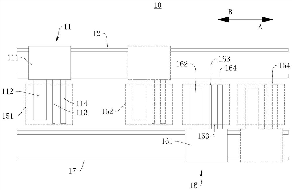
[0035] see figure 1 and figure 2 , figure 1 It is a schematic structural view of the battery continuous winding device 10 provided by the first embodiment of the present invention at a viewing angle. figure 2 It is a schematic structural diagram of the battery continuous winding device 10 provided by the first embodiment of the present invention from another viewing angle. exist figure 1 and figure 2 , the direction indicated by the arrow A is the first direction A, and the direction indicated by the arrow B is the second direction B.

[0036] The first embodiment of the present invention provides a battery continuous winding device 10, the battery continuous winding device 10 is used to wind the pole piece 910 and the diaphragm 920 to form a battery part 930, the battery continuous winding device 10 has the characteristics of high winding efficiency. The battery continuous winding device 10 can be applied to battery production equipment or battery production lines. ...

no. 2 example

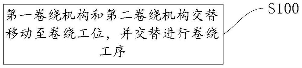
[0069] see image 3 , image 3 It is a schematic flow chart of the battery continuous winding method provided by the second embodiment of the present invention.

[0070] The second embodiment of the present invention provides a continuous winding method for electric cores, and the continuous winding method for electric cores has the characteristics of high winding efficiency. The battery continuous winding method is applied to the battery continuous winding device 10 of the above-mentioned embodiment.

[0071] It should be noted that the basic principles and technical effects of the battery continuous winding method provided in this embodiment are the same as those of the above-mentioned embodiments. Corresponding content in the embodiment.

[0072] The battery continuous winding method, the battery continuous winding method includes:

[0073] Step S100: the first winding mechanism 11 and the second winding mechanism 16 alternately move to the winding station 153, and alte...


PUM


Abstract

The invention discloses a battery core continuous winding device and a battery core continuous winding method, and relates to the technical field of battery core production. The battery core continuous winding device comprises a first winding mechanism, a first guide rail, a second winding mechanism and a second guide rail, wherein the first guide rail and the second guide rail extend along a winding channel, and are positioned at the two sides of the winding channel respectively; the winding channel is provided with a winding preparation section and a winding station; the first winding mechanism and the second winding mechanism can move along the first guide rail and the second guide rail respectively, can move to the winding preparation section and the winding station respectively and can conduct winding work at the winding station to form a battery core piece and conduct winding preparation work at the winding preparation section; and the first winding mechanism and the second winding mechanism can alternately move to the winding section to alternately conduct winding preparation work and winding work. The battery core continuous winding device and the battery core continuous winding method have the characteristic of relatively high winding efficiency.

Description

technical field [0001] The invention relates to the technical field of electric core production, in particular to a continuous winding device for electric cores and a continuous winding method for electric cores. Background technique [0002] With the rapid development of electric vehicles, the demand for lithium batteries is increasing. [0003] Winding, as one of the key technologies in the production of lithium battery cells, has huge advantages, and has higher efficiency under the premise of satisfying the quality of the cells. [0004] However, in the existing battery winding equipment, the battery winding auxiliary time (the time other than the winding time in the winding operation) is generally longer than the winding time, and its winding efficiency is low. [0005] In view of this, it is particularly important to develop and design a battery continuous winding device and a battery continuous winding method that can solve the above technical problems. Contents of ...

Claims


Application Information

Patent Timeline
IPC IPC(8): H01M10/0587H01M10/04H01M10/052
CPCH01M10/0409H01M10/052H01M10/0587Y02E60/10Y02P70/50
Inventor 阳如坤王俊涛张鹏左龙龙魏宏生
Owner GEESUN AUTOMATION TECH
Why Eureka
Try Eureka