
Formwork fixing structure for shear wall at narrow expansion joint

A formwork fixing and shear wall technology, which is applied in formwork/formwork/work frame, building structure, and on-site preparation of building components, can solve the problems of unstable center of gravity of formwork in shear walls, affecting construction, etc. Achieve the effect of reducing the possibility of dumping and increasing stability

Inactive Publication Date: 2020-10-02
江苏建宇建设集团有限公司
View PDF8 Cites 4 Cited by
  • Summary
  • Abstract
  • Description
  • Claims
  • Application Information

AI Technical Summary

Problems solved by technology

[0004] When using the assembled formwork in the prior art, the inner formwork of the shear wall is installed in the expansion joint, the outer formwork of the shear wall is installed on the lower concrete side wall, and the prefabricated wall-through bolts are used to pass through the outer formwork of the shear wall and the shear wall. The inner formwork of the force wall is connected with the outer nut and the inner nut screw, and then the concrete is poured between the inner formwork of the shear wall and the outer formwork of the shear wall, but in actual construction, due to the inner formwork of the shear wall and the shear wall The outer formwork is in contact with the lower concrete side wall and top wall respectively. When the height and mass of the shear wall outer formwork and the shear wall inner formwork are relatively high, the area where the shear wall outer formwork and the lower concrete side wall conflict When it is small, the center of gravity of the inner formwork of the shear wall is easy to be unstable, and the outer formwork of the shear wall and the inner formwork of the shear wall are easy to fall to the side of the shear wall, which affects the construction and needs to be improved

Method used


Image

  • Formwork fixing structure for shear wall at narrow expansion joint
  • Formwork fixing structure for shear wall at narrow expansion joint
  • Formwork fixing structure for shear wall at narrow expansion joint

Examples


Embodiment

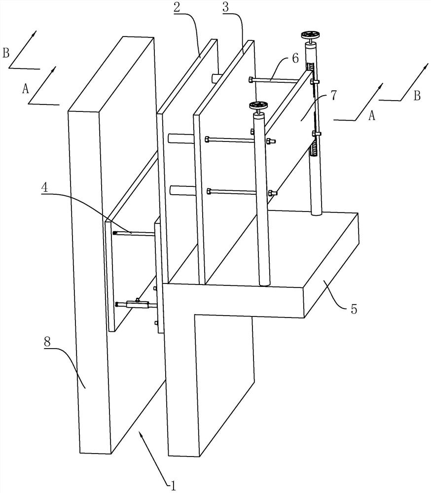
[0041] refer to figure 1 , a formwork fixing structure for a shear wall at a narrow expansion joint, which includes a fixing assembly 3 arranged in an expansion joint 1 and used to limit the formwork 2 in the shear wall, the formwork 2 in the shear wall and the shear wall The outer formwork 4 of the force wall is provided with a connection assembly 6 for installing the inner formwork 2 of the shear wall and the outer formwork 4 of the shear wall on the top wall of the lower concrete 5 .

[0042] refer to figure 1 , the top wall of the lower concrete 5 is provided with a support frame 7, the support frame 7 is connected with the connecting assembly 6, and the support frame 7 is located on the side of the shear wall inner formwork 2 away from the shear wall outer formwork 4; during construction, first place the The fixing component 3 is installed in the expansion joint 1, and then the shear wall inner formwork 2 is installed on the top wall of the lower concrete 5, the shear wa...


PUM


Abstract

The invention discloses a formwork fixing structure for a shear wall at a narrow expansion joint, relates to a building auxiliary device for the shear wall, and aims to solve the problem that a shearwall inner formwork and a shear wall outer formwork are prone to toppling in the prior art. According to the technical scheme, the formwork fixing structure is characterized by comprising a fixing assembly and a connecting assembly which are arranged in the expansion joint; a supporting frame is arranged on the top wall of a lower concrete layer and located on the side, away from the shear wall outer formwork, of the shear wall inner formwork, and the connecting assembly is connected with the supporting frame. In the mode, the shear wall inner formwork and the shear wall outer formwork can besupported at the same time, the possibility that the shear wall outer formwork and the shear wall inner formwork are prone to toppling is reduced, and reduction of construction convenience is facilitated.

Description

technical field [0001] The invention relates to a construction auxiliary device for a shear wall, and more particularly, to a formwork fixing structure for a shear wall at a narrow expansion joint. Background technique [0002] Shear walls are also known as wind-resistant walls, earthquake-resistant walls or structural walls; walls in houses or structures that mainly bear horizontal loads and vertical loads (gravity) caused by wind loads or earthquakes to prevent structural shear (shear) damage . Nowadays, high-rise shear wall structures have been used more and more. Under the influence of site and building layout, high-rise shear wall structures need to leave expansion joints during construction due to the design of excess length or different structural foundations. [0003] The Chinese patent whose authorized notification number is CN205276867U discloses an assembled formwork for expansion joints, the assembled formwork includes a shear wall inner formwork and a shear wal...

Claims


Application Information

Patent Timeline
IPC IPC(8): E04G11/18
CPCE04G11/18
Inventor 张帮华张天桃金大德黄益宝郭正基
Owner 江苏建宇建设集团有限公司
Learn More