
A connecting tank for c-type liquid tank liquefied gas ship

A technology for liquefied gas carriers and liquid tanks, which is applied in the directions of bulk cargo, some tanks in the hull, and the hull of the hull, can solve the problems such as the reduction of the layout size of the liquid cargo tanks, the damage to the heel, the danger of damage to the stability of the tank, etc., and achieve the weight of the ship. The effect of uniform distribution, reducing stress concentration and improving damage stability

Active Publication Date: 2021-08-24
JIANGNAN SHIPYARD GRP CO LTD
View PDF6 Cites 0 Cited by
  • Summary
  • Abstract
  • Description
  • Claims
  • Application Information

AI Technical Summary

Problems solved by technology

Under the requirement of a certain amount of ballast, the top side ballast tank reduces the stability of the ballast condition, while the new IGC code clearly requires that the ballast condition be included in the calculation of the damage stability. In the case of simultaneous damage, if the ballast tank is not damaged simultaneously, extreme damage heel will occur, and the stability of the damaged tank is very dangerous
At the same time, the pipes or pipes connected up and down are often located at the transverse bulkhead with large shear force, which is very prone to deformation and leakage
[0004] The patent application number is CN201920753318.5, and the patent name is a utility model patent for a ballast tank structure and a ship. The load tank is connected with the right bottom ballast tank through the right connecting tank, so that when the cargo tank is damaged, the top ballast tank, the connecting tank and the bottom ballast tank will be damaged at the same time, so as to improve the damage safety performance. However, The utility model patent also discloses that the top ballast tank, the bottom ballast tank and the connecting tank have the same length (along the length direction of the hull), that is, the left top ballast tank, the left bottom ballast tank and the left connecting tank The tanks are of the same length, the right top side ballast tank, the right bottom side ballast tank and the right connecting tank are of the same length, so as to completely isolate the cargo tank from the side shell, resulting in the length of the connecting tank being longer than that of the cargo tank, which This design will definitely make the connecting tank occupy the installation space of the cargo tank in the cargo tank, that is, in order to install the connecting tank with the same length as the top side ballast tank, the maximum liquid cargo tank that can be installed in the cargo tank will be reduced, that is, the layout size of the cargo tank will be reduced , to reduce the utilization rate of cargo tank capacity; in addition, it can be seen from the drawings of the utility model patent that the width of the top surface and the width of the bottom surface of the left connecting tank are respectively smaller than the width of the bottom surface of the left top ballast tank and the width of the top surface of the left bottom ballast tank, and the width of the right The width of the top surface and bottom surface of the connecting tank is smaller than the width of the bottom surface of the right top ballast tank and the top surface width of the right bottom ballast tank respectively, that is, there is a sudden change in section at the connection between the top ballast tank, the bottom ballast tank and the connecting tank situation, prone to stress concentration

Method used

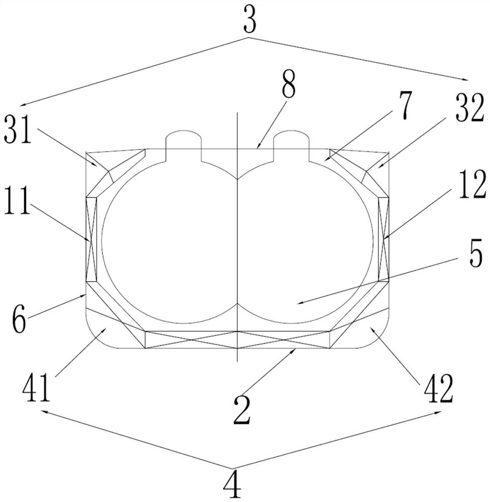
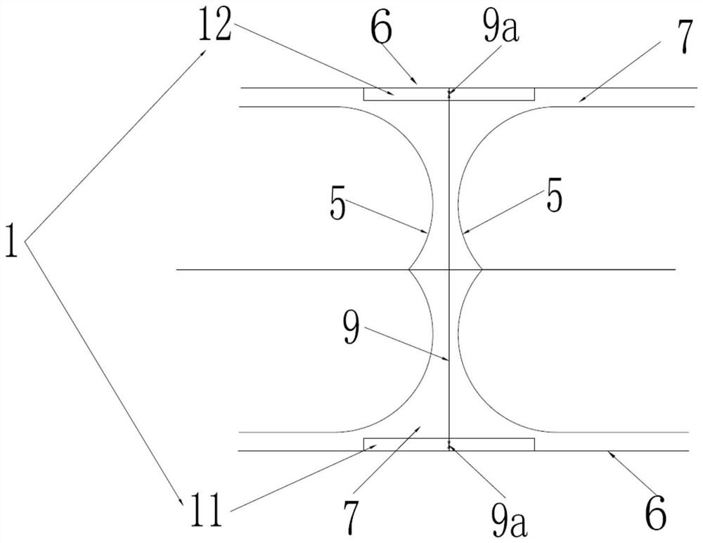
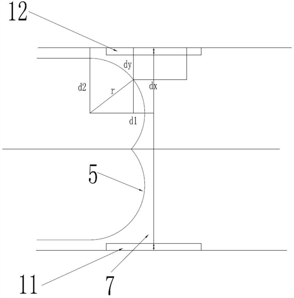

Image

  • A connecting tank for c-type liquid tank liquefied gas ship
  • A connecting tank for c-type liquid tank liquefied gas ship
  • A connecting tank for c-type liquid tank liquefied gas ship

Examples


Embodiment Construction

[0030] The implementation of the present invention will be illustrated by specific specific examples below, and those skilled in the art can easily understand other advantages and effects of the present invention from the contents disclosed in this specification.

[0031] see Figure 1 to Figure 4 . It should be noted that the structures, proportions, sizes, etc. shown in the drawings attached to this specification are only used to match the content disclosed in the specification, for those who are familiar with this technology to understand and read, and are not used to limit the implementation of the present invention. Limiting conditions, so there is no technical substantive meaning, any modification of structure, change of proportional relationship or adjustment of size, without affecting the effect and purpose of the present invention, should still fall within the scope of the present invention. The disclosed technical content must be within the scope covered. At the sa...


PUM


Abstract

The invention provides a connecting tank for a C-type liquid tank liquefied gas ship. The connecting tank includes a left connecting tank for connecting the left top ballast tank and a left bottom ballast tank, The right connecting tank of the load tank and the right bottom ballast tank; the left connecting tank and the right connecting tank are relatively arranged on the left and starboard sides; the front and rear ends of the left connecting tank and the right connecting tank are respectively located at two adjacent Inside the cargo hold, and the front and rear ends of the left and right connecting tanks are symmetrical with respect to the transverse bulkhead between the two adjacent cargo holds; the vertical distance from the front and rear ends of the left and right connecting tanks to the transverse bulkhead The distance s should satisfy: in order to improve the damage stability of the ship while ensuring the utilization rate of the cargo hold capacity.

Description

technical field [0001] The invention belongs to the technical field of communication design of ship ballast tanks, and in particular relates to a communication tank for a C-type liquid tank liquefied gas ship. Background technique [0002] In recent years, the rapid development of the global liquefied gas market has promoted the rapid development of liquefied gas carriers and directly promoted the continuous innovation of the technical solutions of this type of ship. With the continuous maturity of technical solutions, the liquid tanks of liquefied gas ships are getting larger and fewer, and the number of liquid tanks is getting smaller and smaller, which has significantly improved the weight of the empty ship, the complexity of the system and the cost. . [0003] However, in these continuously optimized ship designs, stability is the most basic performance of ships, and its stability margin is being continuously compressed. On the other hand, new rules and regulations fro...

Claims


Application Information

Patent Timeline
Patent Type & Authority Patents(China)
IPC IPC(8): B63B11/04B63B25/12B63B43/06
CPCB63B11/04B63B25/12B63B43/06
Inventor 范鹏武姗郑双燕
Owner JIANGNAN SHIPYARD GRP CO LTD
Learn More