
Antenna module, terminal equipment and manufacturing method of antenna module

A technology of an antenna module and a manufacturing method, which is applied in the directions of manufacturing antenna array devices, antennas, and antenna arrays, can solve problems such as antenna module conflicts, and achieve the effects of improving radiation bandwidth, radiation efficiency, and communication quality.

Active Publication Date: 2020-09-29
BEIJING XIAOMI MOBILE SOFTWARE CO LTD
View PDF8 Cites 1 Cited by
  • Summary
  • Abstract
  • Description
  • Claims
  • Application Information

AI Technical Summary

Problems solved by technology

However, traditional antenna modules are increasingly in conflict with the demand for bandwidth

Method used


Image

  • Antenna module, terminal equipment and manufacturing method of antenna module
  • Antenna module, terminal equipment and manufacturing method of antenna module
  • Antenna module, terminal equipment and manufacturing method of antenna module

Examples


Embodiment Construction

[0065] Reference will now be made in detail to the exemplary embodiments, examples of which are illustrated in the accompanying drawings. When the following description refers to the accompanying drawings, the same numerals in different drawings refer to the same or similar elements unless otherwise indicated. The implementations described in the following exemplary examples do not represent all implementations consistent with the present invention. Rather, they are merely examples of apparatuses and methods consistent with aspects of the invention as recited in the appended claims.

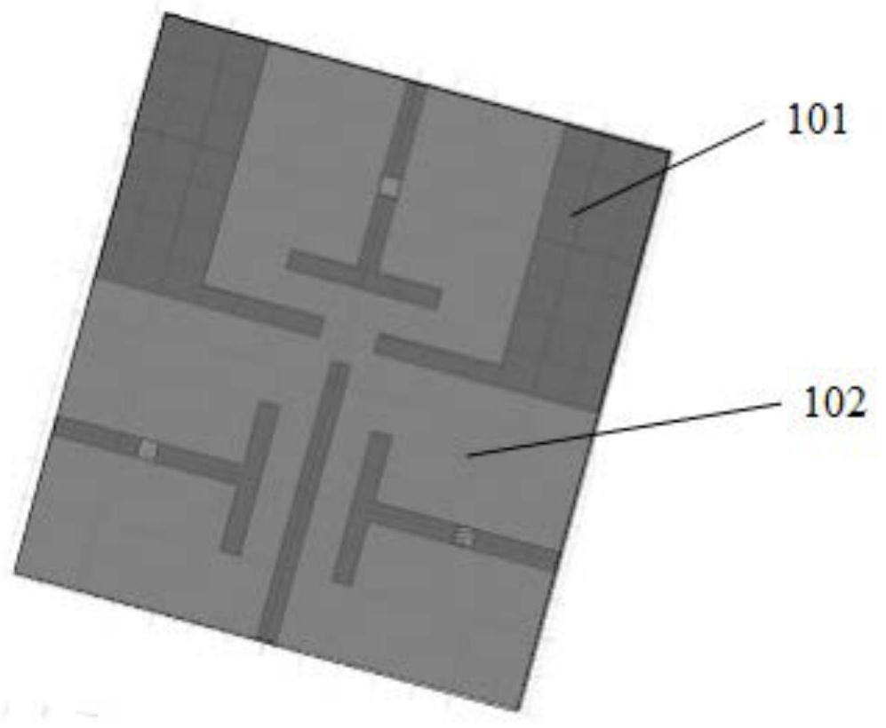
[0066] figure 1 It is a schematic structural diagram of an antenna module shown according to an exemplary embodiment Figure 1 . Such as figure 1As shown, the antenna module is located on a conductive sheet, and the antenna module includes:

[0067] One or more antennas; where,

[0068] The plurality of antenna radiators 102 of the plurality of antennas are formed by different regions of th...


PUM


Abstract

The invention relates to an antenna module, terminal equipment and a manufacturing method of the antenna module. The antenna module is located on a conducting strip, and comprises one or more antennas, wherein a plurality of antenna radiators of a plurality of antennas are formed by different areas of the conducting strip, one antenna radiator of one antenna is composed of at least part of the conducting strip. The antenna module is advantaged in that a plurality of antenna radiators share one conductive sheet, the radiation area of a single antenna radiator can be increased, radiation efficiency and the radiation bandwidth of the antenna radiator are improved, the situation that the antenna radiator is affected by the environment is reduced, only one conducting strip is needed, multiple conducting strips do not need to be independently arranged to receive and transmit wireless signals of multiple frequency bands, then the space occupied by the antenna module in terminal equipment canbe reduced, and the space utilization rate of the terminal equipment is increased.

Description

technical field [0001] The present disclosure relates to the technical field of communication, and in particular, to an antenna module, a terminal device, and a manufacturing method of the antenna module. Background technique [0002] With the rapid development of communication technology and the demand for technology, terminal equipment is increasingly moving toward miniaturization, broadband and the integration of the fourth generation mobile communication technology (the 4th generation mobile communication technology, 4G) and the fifth generation mobile communication technology (the 5th generation mobile communication technology, 5G). However, traditional antenna modules are increasingly in conflict with the demand for bandwidth. Contents of the invention [0003] The present disclosure provides an antenna module, a terminal device and a manufacturing method of the antenna module. [0004] In the first aspect of the embodiments of the present disclosure, the antenna m...

Claims


Application Information

Patent Timeline
IPC IPC(8): H01Q1/36H01Q1/48H01Q1/50H01Q21/00
CPCH01Q1/36H01Q1/50H01Q21/00H01Q1/48H01Q21/0087
Inventor 胡茂程胜祥
Owner BEIJING XIAOMI MOBILE SOFTWARE CO LTD
Learn More