Pull pin with locking function

A functional and locking technology, applied in the direction of bolts, etc., can solve the problems of unexpected situations, unable to pull the pin to be fixed in the locked state, unable to pull the pin to be fixed in the unlocked state, etc., to prevent accidental slippage.

Pending Publication Date: 2020-09-29
ZHEJIANG LINGPAO HEALTH TECH CO LTD
View PDF0 Cites 0 Cited by
  • Summary
  • Abstract
  • Description
  • Claims
  • Application Information

AI Technical Summary

Problems solved by technology

[0002] At present, the traditional pull pin does not have a locking and positioning structure design. When in use, the pull pin is often kept stuck in the pin hole due to the action of the spring, and cannot be fixed in the locked or unlocked state.
When two or more pull pins need to be pulled open at the same time, the pull pins cannot be fixed in the unlocked state one by one, and it is quite inconvenient for a single person to operate; at the same time, the existing pull pins cannot fix the pull pins in the locked state. There are often accidental slippages in the middle, resulting in unexpected situations

Method used


Image

  • Pull pin with locking function
  • Pull pin with locking function

Examples


Embodiment Construction

[0012] The present invention will be described in further detail below in conjunction with the accompanying drawings.

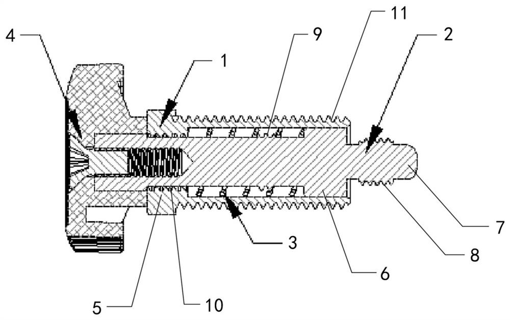
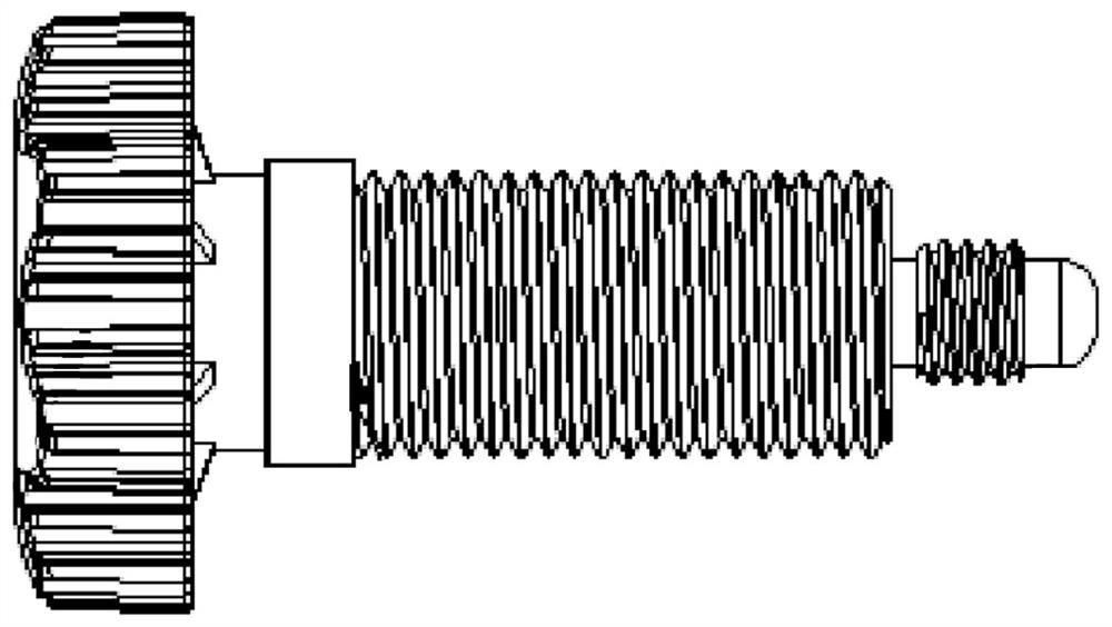
[0013] Such as figure 1 , figure 2 As shown, a pull pin with a locking function includes an outer sleeve 1, an inner rod 2, a spring 3 and a knob 4. The upper end of the outer sleeve 1 is provided with a spring limiting neck portion 5, and the inner rod 2 is provided with The spring clamping part 6, the spring 3 is set on the inner rod 2, and inserted into the outer sleeve 1 together with the inner rod 2, so that one end of the spring 3 is against the spring limit neck part 5, and the other end is against the spring clamping part 6 ; The outer end of the inner rod 2 is connected to the knob 4, and the inner end of the inner rod 2 is set as a chuck 7.

[0014] Further, the pull pin fixing hole 5 is a threaded hole, and the inner end of the inner rod 2 is provided with an external thread 8 fixed to the pull pin fixing hole 5, so that the chuck 7 of the inner...


PUM


Abstract

The invention discloses a pull pin with the locking function. The pull pin comprises an outer sleeve, an inner rod, a spring and a rotary knob; a spring limiting choke is arranged at the upper end ofthe outer sleeve; a spring clamping part is arranged on the inner rod; the spring is arranged on the inner rod in a sleeving manner; the spring and the inner rod are inserted in the outer sleeve together, so that one end of the spring is propped against the spring limiting choke, and the other end of the spring is propped against the spring clamping part; the outer side of the inner rod is connected with the rotary knob; and a chuck is arranged at the inner side end of the inner rod. Compared with the prior art, the pull pin has the following advantages: the pull pin can realize the locking function in the unlocking state and can simultaneously open two or more zippers, and at the same time, the pull pin can be fixed in the locking state to effectively prevent accidental slip.

Description

technical field [0001] The invention relates to a pull pin, in particular to a pull pin with a locking function. Background technique [0002] At present, the traditional pull pin does not have a locking and positioning structure design. When in use, the pull pin is often kept stuck in the pin hole due to the action of the spring, and cannot be fixed in the locked or unlocked state. When two or more pull pins need to be pulled open at the same time, the pull pins cannot be fixed in the unlocked state one by one, and it is quite inconvenient for a single person to operate; at the same time, the existing pull pins cannot fix the pull pins in the locked state. There are often accidental slippages in the middle, resulting in unexpected situations. Therefore, developing a pull pin with a locking function has become an urgent problem to be solved by those skilled in the art. Contents of the invention [0003] The present invention aims to solve the above disadvantages, and pro...

Claims


Application Information

Patent Timeline
Patent Type & Authority Applications(China)
IPC IPC(8): F16B19/02
CPCF16B19/02
Inventor 潘岩君
Owner ZHEJIANG LINGPAO HEALTH TECH CO LTD
Why Eureka
Try Eureka