Eureka AIR delivers breakthrough ideas for toughest innovation challenges, trusted by R&D personnel around the world.

Convenient-to-move wall paint spraying device

A kind of painting equipment and surface fixing technology, which is applied in the direction of painting booth, spraying device, pretreatment surface, etc., can solve the problems of small painting range and poor stability, and achieve the effect of improving painting efficiency, solving poor stability and preventing precipitation

Inactive Publication Date: 2020-09-29
胡海军
View PDF0 Cites 18 Cited by
  • Summary
  • Abstract
  • Description
  • Claims
  • Application Information

AI Technical Summary

Problems solved by technology

[0003] The existing painting equipment has poor stability and a small painting range, which is difficult to meet people's needs

Method used


Image

  • Convenient-to-move wall paint spraying device
  • Convenient-to-move wall paint spraying device
  • Convenient-to-move wall paint spraying device

Examples


Embodiment 1

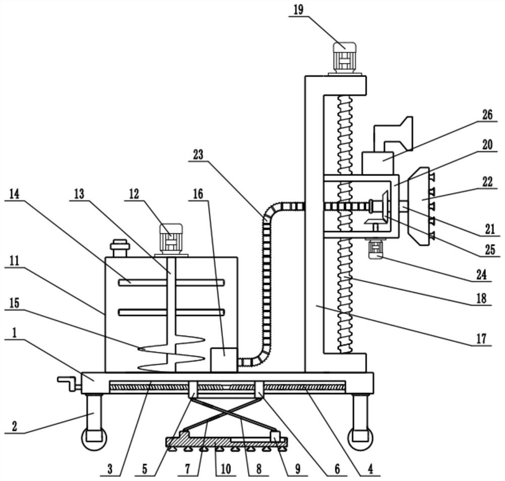
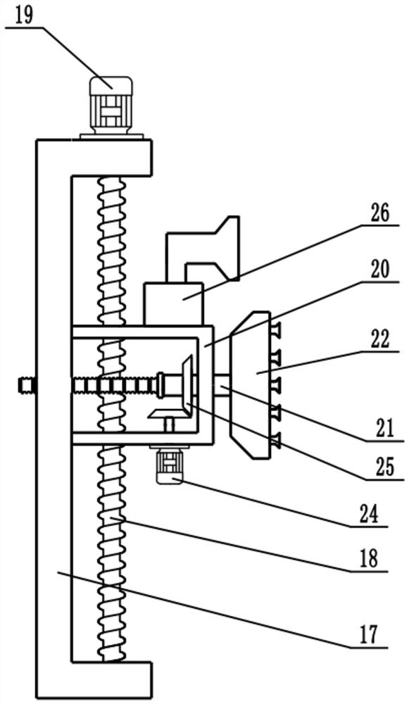
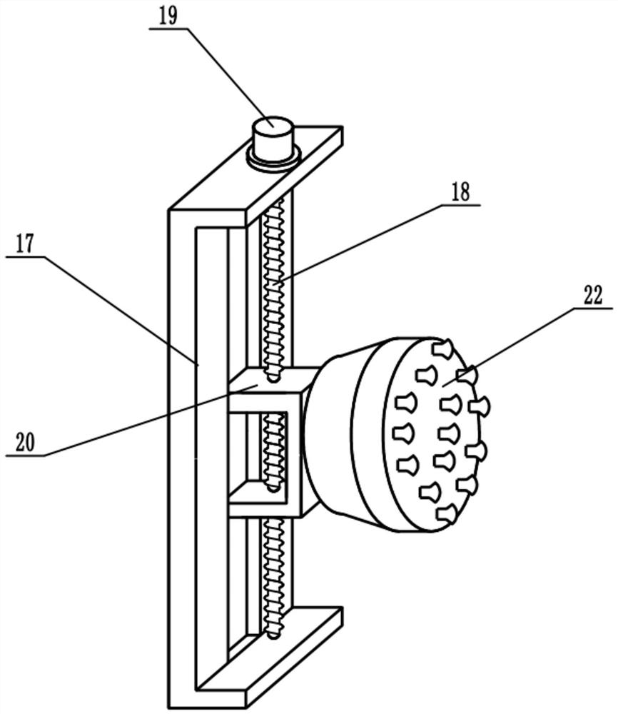
[0022] see Figure 1-3 , in the embodiment of the present invention, a kind of wall surface painting equipment that is convenient to move, comprises frame 1, material storage box 11, booster pump 16, installation frame 17 and nozzle 22, and the bottom of frame 1 is equipped with universal wheel 2 , to facilitate the movement of the device, the upper surface of the frame 1 is fixedly connected with a storage box 11 for storing paint, the inside of the storage box 11 is equipped with a stirring mechanism, the stirring mechanism includes a first motor 12, a stirring shaft 13, Stirring rod 14, spiral plate 15, the top of material storage box 11 is fixedly connected with first motor 12, and the axle extension end of first motor 12 is fixedly connected with stirring shaft 13, and stirring shaft 13 stretches in the material storage box 11, and stirring shaft Stirring rods 14 are distributed on the 13, and a spiral plate 15 is installed on the lower end of the stirring shaft 13. The f...

Embodiment 2

[0024] On the basis of Embodiment 1, a stabilizing mechanism is installed on the bottom of the frame 1, and the stabilizing mechanism includes a two-way screw rod 4, a left slider 5, a right slider 6, a first support rod 7, a second support rod 8, a sliding Block 9 and support plate 10, the bottom of frame 1 is provided with chute 3, and the inside of chute 3 is equipped with two-way screw mandrel 4, and the two ends of two-way screw mandrel 4 are rotationally connected with the side wall of chute 3, two-way screw mandrel 4. The upper sleeve is provided with a left slider 5 and a right slider 6. The left slider 5 and the right slider 6 are threadedly connected with the two-way screw rod 4 respectively. The left slider 5 and the right slider 6 are embedded in the chute 3 respectively. The slider 5 and the right slider 6 are slidably connected with the chute 3 respectively, the left slider 5 and the right slider 6 can slide left and right in the chute 3, the end of the two-way sc...


PUM


Abstract

The invention relates to the field of building equipment, in particular to a convenient-to-move wall paint spraying device. The device comprises a rack, a storage box, a booster pump, a mounting frameand a sprayer. The upper surface of the rack is fixedly connected with the storage box, a stirring mechanism is installed in the storage tank, the bottom of the storage box is also provided with thebooster pump, the upper surface of the rack is fixedly connected with the mounting frame, a lifting lead screw is mounted inside the mounting frame, the interior of the mounting frame is slidably connected with a lifting frame, a hollow rotating shaft penetrates through the lifting frame, and the sprayer is installed at the right end of the hollow rotating shaft. A stabilizing mechanism is mountedat the bottom of the rack. By means of the stabilizing mechanism, the stability of the device is greatly improved, and wall paint spraying is facilitated. Paint is stirred through the stirring mechanism, so that the paint is evenly mixed, and the paint is prevented from being precipitated. The paint in the storage box is conveyed to the sprayer through the booster pump for wall paint spraying. The sprayer is driven by a third motor to rotate, so that the spraying process is more uniform, and the paint spraying efficiency is improved.

Description

technical field [0001] The invention relates to the field of construction equipment, more specifically, a mobile wall painting equipment. Background technique [0002] There are generally two construction methods for wall painting projects: spray painting and brushing. The construction methods of these two wall paints are very different in operation and effect. Spray paint has the advantages of fast construction, good flatness, and no poor texture. The surface of spray paint coating is smooth, high hardness, easy to clean, and colorful. The feeling of board room. [0003] The existing painting equipment has poor stability and a small painting range, which is difficult to meet people's needs. Contents of the invention [0004] The purpose of the present invention is to provide a mobile wall painting equipment to solve the problems raised in the above background technology. [0005] To achieve the above object, the present invention provides the following technical soluti...

Claims


Application Information

Patent Timeline
Patent Type & Authority Applications(China)
IPC IPC(8): B05B9/04B05B12/16B05B13/04B05B15/00B05B15/25B05B16/20B05D3/04E04F21/08
CPCB05B9/0403B05B13/041B05B13/0421B05B15/00B05D3/0413B05B12/16B05B15/25B05B16/20E04F21/08
Inventor 胡海军
Owner 胡海军
Why Eureka
Eureka Blog
Learn More