Selective auxiliary lifting type storey height adjusting storage shelf and control method thereof
An auxiliary lifting and selective technology, applied in the direction of display shelves, display hangers, display tables, etc., can solve the problems of inconvenient adjustment of shelf height and low degree of automation of floor height adjustment, so as to ensure the combination stability and simple and convenient control , the effect of supporting stability
- Summary
- Abstract
- Description
- Claims
- Application Information
AI Technical Summary
Problems solved by technology
Method used
Image
Examples
Embodiment 1
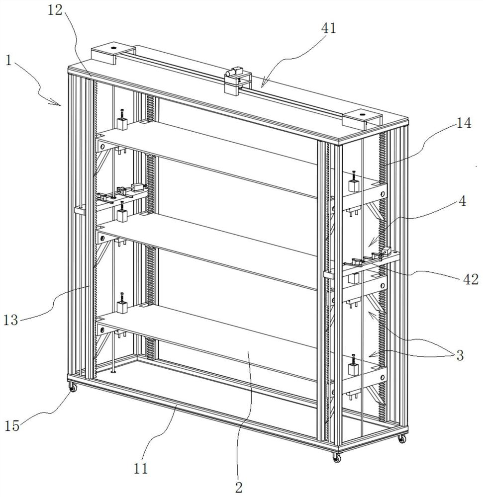
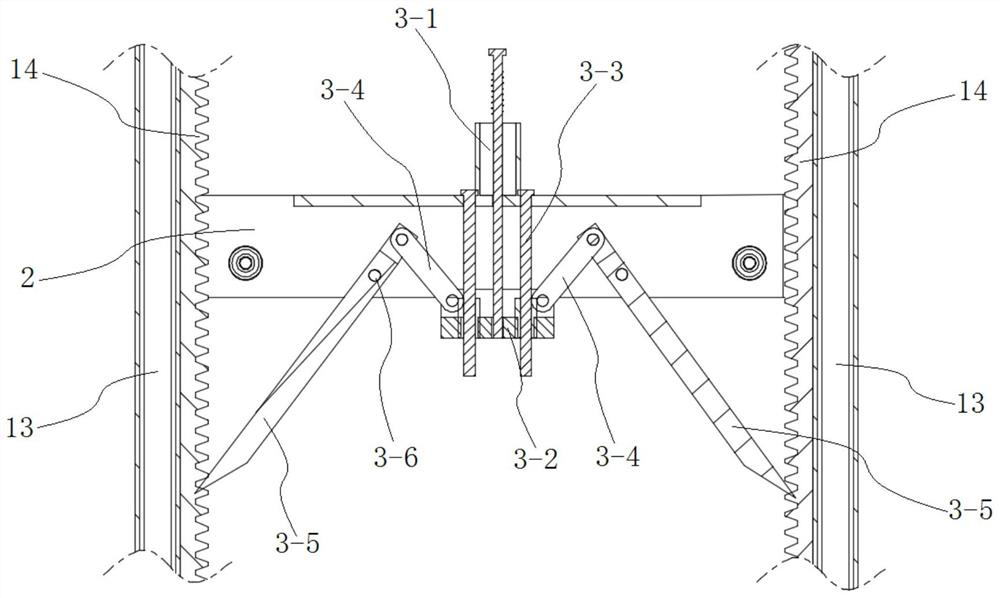
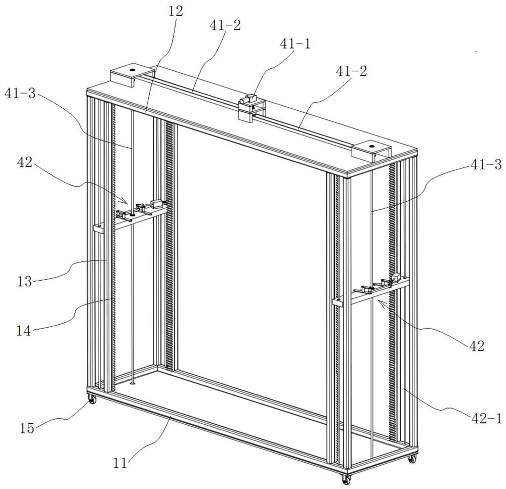
[0053] combine Figure 1 to Figure 4 As shown, a selective auxiliary lift-type storey height adjustment storage shelf in this embodiment includes a rectangular frame 1 and several shelves 2 installed on the rectangular frame 1, the rectangular frame 1 is the main part of the shelf, and the shelf 2 is used for Separate the storage space of the rectangular frame 1 for storing goods; the rectangular frame 1 includes a bottom frame 11, a top frame 12, and a column 13 installed between the bottom frame 11 and the top frame 12, the bottom frame 11, the top frame 12 and the column 13 are connected to form a rectangular frame structure; in order to facilitate the overall movement of the shelf, casters 15 with self-locking function are also provided at the bottom of the bottom frame 11 of the rectangular frame 1, which facilitates the movement of the shelf position. Different from traditional storage racks, the storage rack with selective auxiliary lifting height adjustment in this emb...
Embodiment 2
[0062] combine Figure 5 and Figure 6As shown, a selective auxiliary lift-type storey height adjustment storage shelf in this embodiment has the same basic structure as that in Embodiment 1, the difference is that in this embodiment, the lifting drive mechanism 41 adopts a top traction mechanism, including lifting Drive motor two 41-1', driving drive shaft 41-2', driven drive shaft 41-3', synchronous belt transmission mechanism two 41-4', winding wheel 41-5' and traction belt 41-6', The lifting drive motor 2 41-1' is installed on the top of the rectangular frame 1, and two driven transmission shafts 41-3' are arranged in parallel on the top of the rectangular frame 1, and the two ends of the two driven transmission shafts 41-3' Winding wheels 41-5' are respectively provided, and a traction belt 41-6' is provided on the winding wheels 41-5', and the traction belt 41-6' is connected with the lifting seat plate 42-2 of the lifting mechanism 42 on the corresponding side The out...
Embodiment 3
[0068] combine Figure 7 , Figure 8 and Figure 9 As shown, a selective auxiliary lift-type storey height adjustment storage shelf of this embodiment has the same basic structure as that of Embodiment 1, the difference is that: in this embodiment, the lift drive mechanism 41 adopts a scissor lift mechanism, and On both sides of the rectangular frame 1 are respectively provided with a set of lifting drive mechanism 41 that cooperates with the lifting mechanism 42 on the corresponding side; The telescopic assembly 41-3", the upper bracket 41-4", the lower slider 41-5", the upper slider 41-6" and the transmission screw 41-7", the scissor type telescopic assembly 41-3" consists of several hinged The "X"-shaped connecting rod unit is hinged and formed. The lower bracket 41-2" is fixed on the bottom of the rectangular frame 1, and a horizontal guide rod is arranged on the lower bracket 41-2". The ends of the rods are slidably installed on the horizontal guide rods on the lower b...
PUM
 Abstract
Description
Claims
Application Information
 - R&D Engineer
- R&D Manager
- IP Professional
- Industry Leading Data Capabilities
- Powerful AI technology
- Patent DNA Extraction
Browse by: Latest US Patents, China's latest patents, Technical Efficacy Thesaurus, Application Domain, Technology Topic, Popular Technical Reports.
© 2024 PatSnap. All rights reserved.Legal|Privacy policy|Modern Slavery Act Transparency Statement|Sitemap|About US| Contact US: help@patsnap.com


